7-21
7-6 Register Number Allocations in Detail
The following description provides information on register numbers allocated to the
Inverter and the meanings of the registers. As for the register numbers of the parameters
(n001 through n179), refer to Section 10 List of Parameters and the description of each
of these parameters wherever explained in this manual.
7-6-1 I/O Function
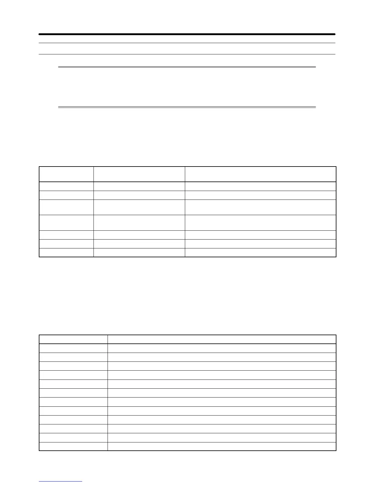
H Communications with a Single Slave with Addresses 01 to 32
(01 to 20 Hex) Read/Write
Register No.
(Hex)
Function Description
0000 Not used. ---
0001 RUN command Refer to the table below.
0002 Frequency reference Set the frequency reference in the unit according to
the set value in n152.
0003 V/f gain Set on condition that 100% is 1000 within a range
from 2.0 to 200.0% (20 to 2000). (See note 1.)
0004 to 0008 Not used. ---
0009 Inverter output Refer to the table below.
000A to 000F Not used. ---
Note 1. The V/f gain is a rate to be multiplied by the output voltage obtained from V/f operation. If 1000
(03E8 Hex) is set, the multiplication rate will be 1.
Note 2. When the above registers are read, values that are set through communications will be read.
For example, when the RUN command (register 0001) is read, the control input in the register
that was previously set through communications will be returned. This is not a value moni-
tored through the input signal terminal.
D RUN Command (Register 0001 Hex)
Bit No. Function
0 RUN command (1: RUN)
1 Forward/Reverse (1: Reverse)
2 External fault (External fault EF0)
3 Fault reset (1: Fault reset)
4 Multi-function input 1 (1: ON)
5 Multi-function input 2 (1: ON)
6 Multi-function input 3 (1: ON)
7 Multi-function input 4 (1: ON)
8 Multi-function input 5 (1: ON)
9 Multi-function input 6 (1: ON)
10 Multi-function input 7 (1: ON)
11 to 15 Not used.
Communications Chapter 7

 Loading...


