8-2
8-1 Protective and Diagnostic Functions
8-1-1 Fault Detection (Fatal Errors)
The Inverter will detect the following faults if the Inverter or motor burns or the internal
circuitry of the Inverter malfunctions. When the Inverter detects a fault, the fault code will
be displayed on the Digital Operator, the fault contact output will operate, and the
Inverter output will be shut off causing the motor to coast to a stop. The stopping method
can be selected for some faults, and the selected stopping method will be used with
these faults. If a fault has occurred, refer to the following table to identify and correct the
cause of the fault. Use one of the following methods to reset the fault after restarting the
Inverter. If the operation command is being input, however, the reset signal will be ig-
nored. Therefore, be sure to reset the fault with the operation command turned OFF.
• Turn ON the fault reset signal. A multi-function input (n050 to n056) must be set to 5
(Fault Reset).
• Press the STOP/RESET Key on the Digital Operator.
• Turn the main circuit power supply OFF and then ON again.
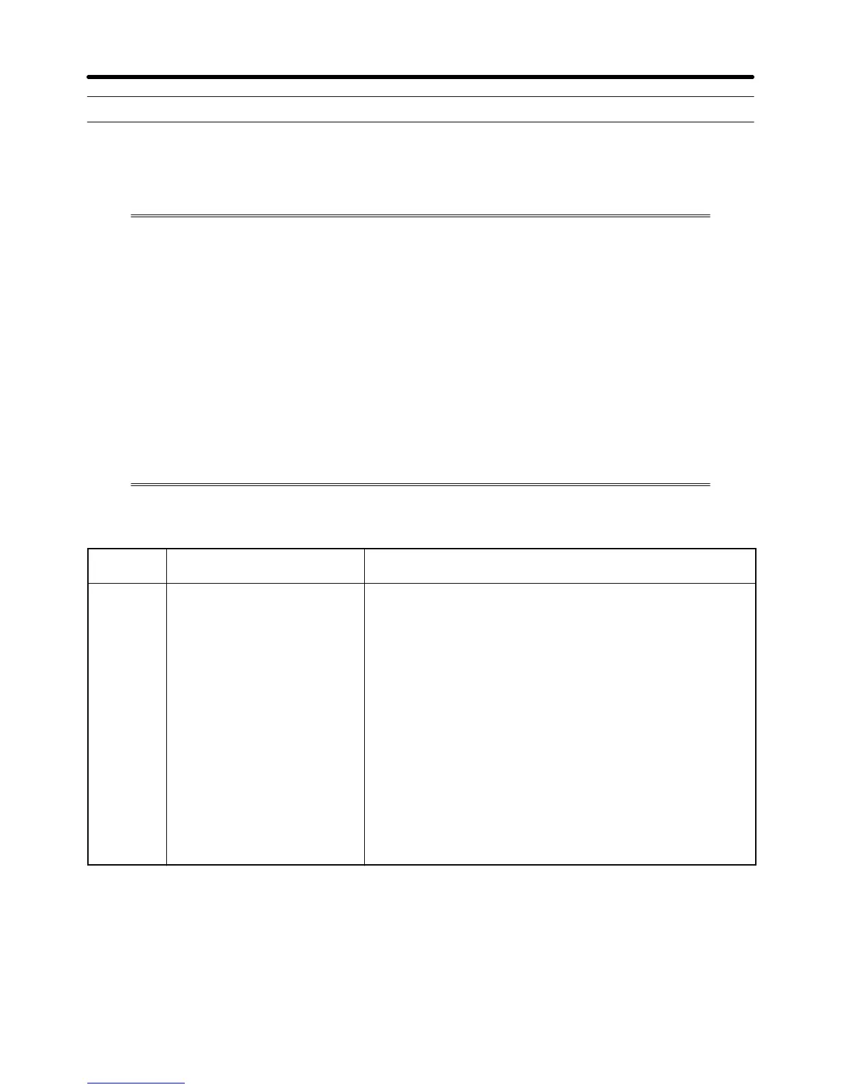
H Fault Displays and Processing
Fault
display
Fault name and meaning Probable cause and remedy
%c
Overcurrent (OC)
The Inverter output current is
as high as or higher than
250% of the rated output
current.
• A short-circuit or ground fault has occurred and at the
Inverter output.
→ Check and correct the motor power cable.
• The V/f setting is incorrect.
→ Reduce the V/f set voltage.
• The motor capacity is too large for the Inverter.
→ Reduce the motor capacity to the maximum applicable
motor capacity.
• The magnetic contactor on the output side of the Inverter
has been opened and closed.
→ Rearrange the sequence so that the magnetic contactor
will not open or close while the Inverter has current
output.
• The output circuit of the Inverter is damaged.
→ Replace the Inverter.
Maintenance Operations Chapter 8

 Loading...


