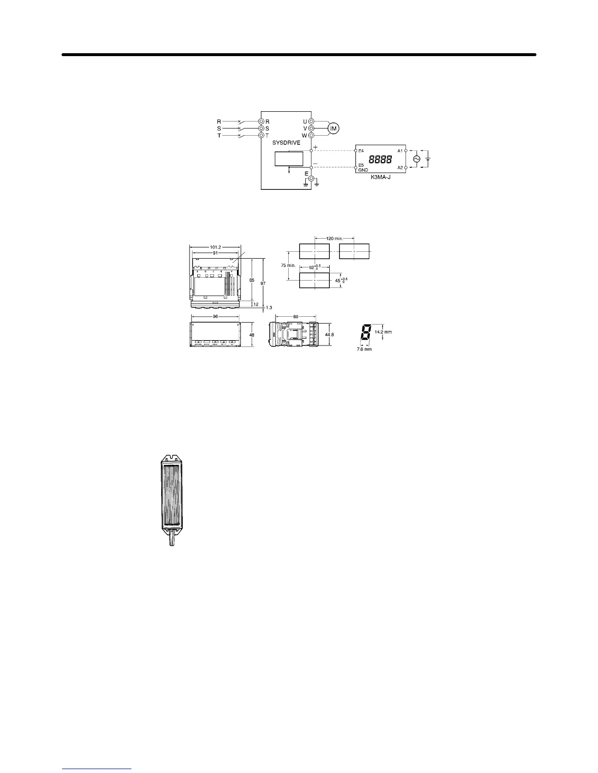
EasyManuals Logo

Omron SYSDRIVE 3G3MV SERIES User Manual

Omron SYSDRIVE 3G3MV SERIES
344 pages
To Next Page IconTo Next Page
To Previous Page IconTo Previous Page
Page #280 background imageLoading...
Page #280 background image
9-12
H Wiring Example
Three-phase
power supply
Circuit breaker
for wiring
Inverter’s
internal
circuitry
Analog
monitor
–10 to +10 V DC
Analog output
H External Dimensions (mm)
Recommended panel cutout
Terminal cover
(included)
Main display LED size
Terminals: M3, Terminal cover included.
9-2-5 Braking Resistor
H 3G3IV-PERFj
Uses a resistor to absorb regenerative energy
of the motor to reduce deceleration time.
(Usage rate: 3% ED.)
Note “Usage rate: 3% ED” indicates that the
deceleration time can be reduced by
3% of the operating time of one cycle.
Refer to 2-2-3 Wiring around the Main Circuit
for precautions when selecting the Braking
Resistor.
Specifications
Chapter 9

Table of Contents

Questions and Answers:

Question and Answer IconNeed help?

Do you have a question about the Omron SYSDRIVE 3G3MV SERIES and is the answer not in the manual?

Omron SYSDRIVE 3G3MV SERIES Specifications

General IconGeneral
ModelSYSDRIVE 3G3MV SERIES
CategoryInverter
Input Frequency50/60 Hz
Output Frequency0.1 to 400 Hz
Cooling MethodForced Air Cooling
Input Voltage200 to 240 VAC, 380 to 480 VAC
Horsepower Range0.1 to 15 HP
Power Range0.1 to 11 kW
Overload Capacity150% for 60 seconds
Braking UnitBuilt-in
Protection FunctionsOvercurrent, Overvoltage, Undervoltage, Overheat
CommunicationRS-485
Ambient Temperature-10 to 50°C
Storage Temperature-20 to 65°C
Humidity5 to 95% RH (non-condensing)
Vibration5.9 m/s² or less
Voltage Class200V, 400V

Related product manuals