7-22
Note There is an OR relationship between input from the control terminals and input through commu-
nications. Therefore, if multi-function inputs of this register are set to forward/stop and reverse/
stop, it is possible to execute the RUN command through the multi-function inputs. These settings
are not, however, recommended because these settings establish two command lines.
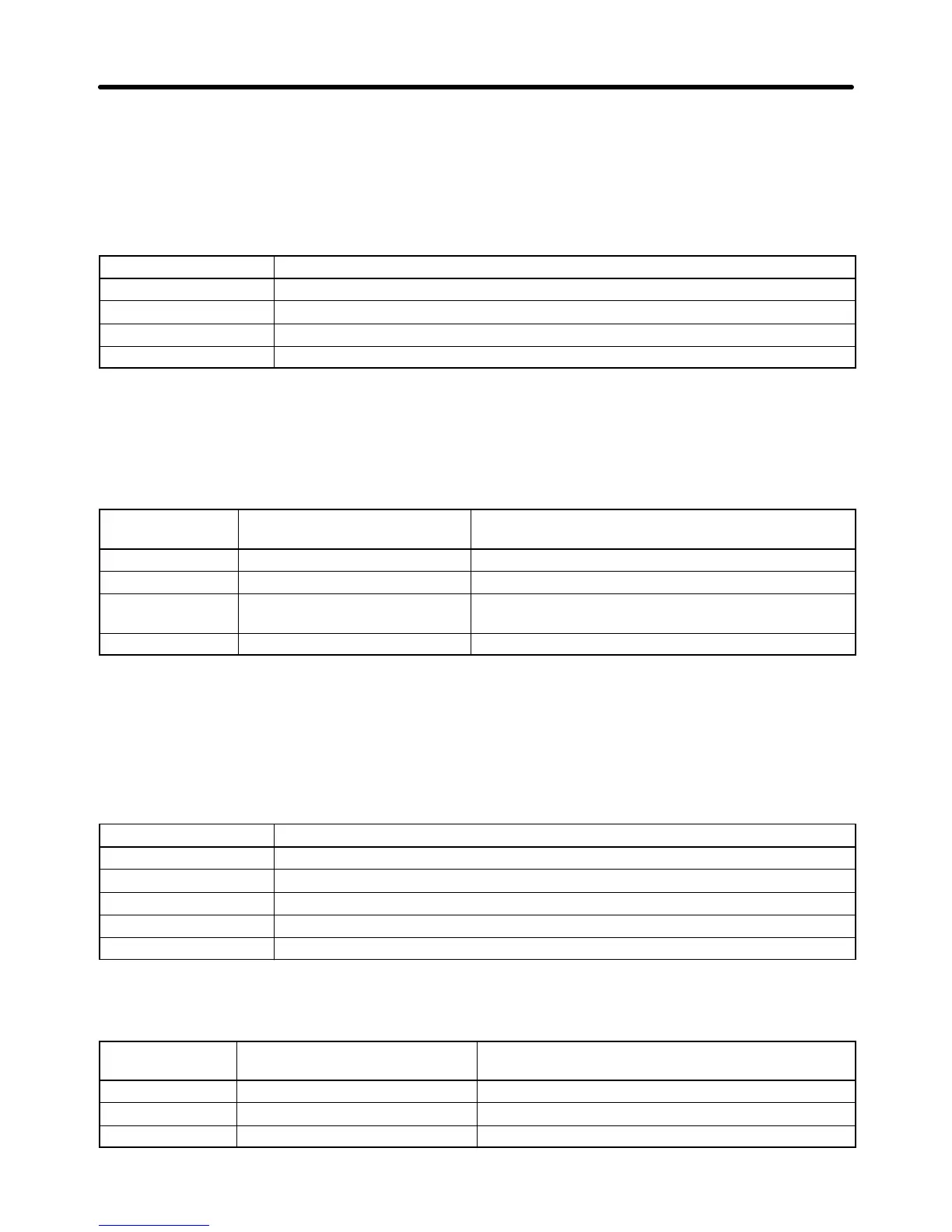
D Inverter Output (Register 0009 Hex)
Bit No. Function
0 Multi-function contact output (1: ON)
1 Multi-function output 1 (1: ON)
2 Multi-function output 2 (1: ON)
3 to 15 Not used.
Note The settings will be enabled if multi-function outputs 1 through 3 in n057 through n059 are set to
18 for communications output. Then the corresponding output terminal will be turned ON and
OFF through communications.
H Broadcast Message with Slave Address: 00 (00 Hex) Write
Register No.
(Hex)
Function Description
0000 Not used. ---
0001 RUN command Refer to the table below.
0002 Frequency reference Set the frequency reference based on the maximum
frequency as 30,000.
0003 to 000F Not used. ---
Note 1. Data can be written to registers 0001 and 0002 only.
Note 2. No data can be written to multi-function input.
Note 3. The unit of setting of the broadcast message is different from that in the DSR message to com-
municate with a single Slave.
D RUN Command (Register 0001 Hex)
Bit No. Function
0 RUN command (1: RUN)
1 Forward/Reverse (1: Reverse)
2 External fault (1: External fault EF0)
3 Fault reset (1: Fault reset)
4 to 15 Not used.
7-6-2 Monitor Functions
Register No.
(Hex)
Function Description
0020 Status signal Refer to the following corresponding table.
0021 Fault status 1 Refer to the following corresponding table.
0022 Data link status Refer to the following corresponding table.
Communications Chapter 7

 Loading...


