8-10
8-1-2 Warning Detection (Nonfatal Errors)
The warning detection is a type of Inverter protective function that does not operate the
fault contact output and returns the Inverter to its original status once the cause of the
error has been removed. The Digital Operator flashes and display the detail of the error.
If a warning occurs, take appropriate countermeasures according to the table below.
Note Some warnings or some cases stop the operation of the Inverter as described in
the table.
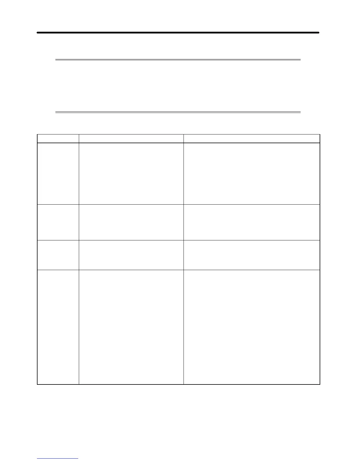
H Warning Displays and Processing
Fault display Warning name and meaning Probable cause and remedy
uU
(flashing)
Main circuit undervoltage (UV)
The main circuit DC voltage has
reached the undervoltage detection
level (200 V DC for the 3G3MV-A2j,
160 V DC for the 3G3MV-ABj, and
400 V DC for the 3G3MV-A4j).
• Power supply to the Inverter has phase loss,
power input terminal screws are loose, or the
power line is disconnected.
→ Check the above and take necessary
countermeasures.
• Incorrect power supply voltage
→ Make sure that the power supply voltage is
within specifications.
%U
(flashing)
Main circuit overvoltage
The main circuit DC voltage has
reached the overvoltage detection
level (410 V DC for 200-V Inverters,
820 V DC for 400-V Inverters).
• The power supply voltage is too high.
→ Decrease the voltage so it will be within
specifications.
%h
(flashing)
Radiation fin overheated (OH)
The temperature of the radiation fins
of the Inverter has reached 110_C ±
10_C.
• The ambient temperature is too high.
→ Ventilate the Inverter or install a cooling unit.
cal
(flashing)
Communications standby (CAL)
No normal DSR message has been
received during RS-422/4895
communications.
The Inverter detects this warning only
when RUN command selection (n003)
is set to 2 or frequency reference
selection (n004) is set to 6. Until the
warning is reset, no input other than
communications input will be ignored.
• A short-circuit, ground fault, or disconnection has
occurred on the communications line.
→ Check and correct the line.
• The termination resistance setting is incorrect.
→ In the case of RS-422 communications, set
pin 1 of SW2 of all Inverters to ON. In the
case of RS-485 communications, set pin 1 of
SW2 of only the Inverter located at each end
of the network to ON.
• Master’s program error.
→ Check the start of communications and
correct the program.
• Communications circuit damage.
→ If the same error is detected as a result of a
self-diagnostic test, change the Inverter.
Maintenance Operations Chapter 8

 Loading...


