2-36
Note 1. Always separate the control signal line from the main circuit cables and other power cables.
Note 2. Do not solder the wires to the control circuit terminals. The wires may not contact well with the
control circuit terminals if the wires are soldered.
Note 3. The end of each wire connected to the control circuit terminals must be stripped for approxi-
mately 5.5 mm.
Note 4. Connect the shield to the ground terminal of the Inverter. Do not ground the shield on control
side.
Note 5. Cover the shield with tape so that the shield will not come into contact with other signal wires
or machines.
Control circuit terminal
block
Thin-slotted screwdriver
Strip the end for 5.5 mm if no
solderless terminal is used.
Wires
Solderless terminal or
wire without soldering
Note Applying a torque of greater than 0.5 NSm
may damage the terminal block. If the
tightening torque is insufficient, however,
wires may be disconnected.
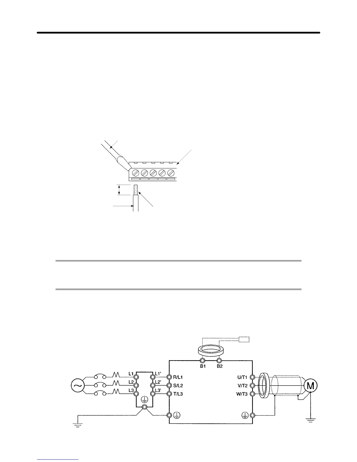
2-2-5 Conforming to EC Directives
The following description provides the wiring method of the Inverter to meet EC Directive
requirements. If the following requirements are not satisfied, the whole equipment incor-
porating the Inverter will need further confirmation.
H Standard Connection
D Main Circuit Terminals
Line breakers
3-phase 200 V AC, single-phase
200 V AC, or 3-phase 400 V AC
Noise Filter
Clamp core
Clamp core
Braking Resistor
(optional)
Design Chapter 2

 Loading...


