2-35
D Wires and Tightening Torque
Multi-function Contact Output (MA, MB, and MC)
Terminal
screw size
Tightening
torque
N S m
Wire Wire size mm
2
(AWG)
Recommended
wire size mm
2
(AWG)
Cable
M3 0.5 to 0.6
Single wire 0.5 to 1.25 (20 to 16)
0.75 (18) Cable with
Stranded wire 0.5 to 1.25 (20 to 16)
po
ye
y
ene
sheath
Sequential Input (S1 through S7 and SC), Multi-function Photocoupler Output (P1,
P2, PC), RS-422/485 Communications (R+, R–, S+, S–) and Multi-function Analog
Output (AM or AC), and Pulse Train Input (RP)
Terminal
screw size
Tightening
torque
N S m
Wire Wire size mm
2
(AWG)
Recommended
wire size mm
2
(AWG)
Cable
M2 0.22 to 0.25
Single wire 0.5 to 1.25 (20 to 16)
0.75 (18) Cable with
Stranded wire 0.5 to 0.75 (20 to 18)
po
ye
y
ene
sheath
Frequency Reference Input (FR, FS, and FC)
Terminal
screw size
Tightening
torque
N S m
Wire Wire size
mm
2
(AWG)
Recommended
wire size mm
2
(AWG)
Cable
M2 0.22 to 0.25
Single wire 0.5 to 1.25 (20
to 16)
0.75 (18) Special cable with
polyethylene sheath and
Stranded wire 0.5 to 0.75 (20
to 18)
shield for measurement
use
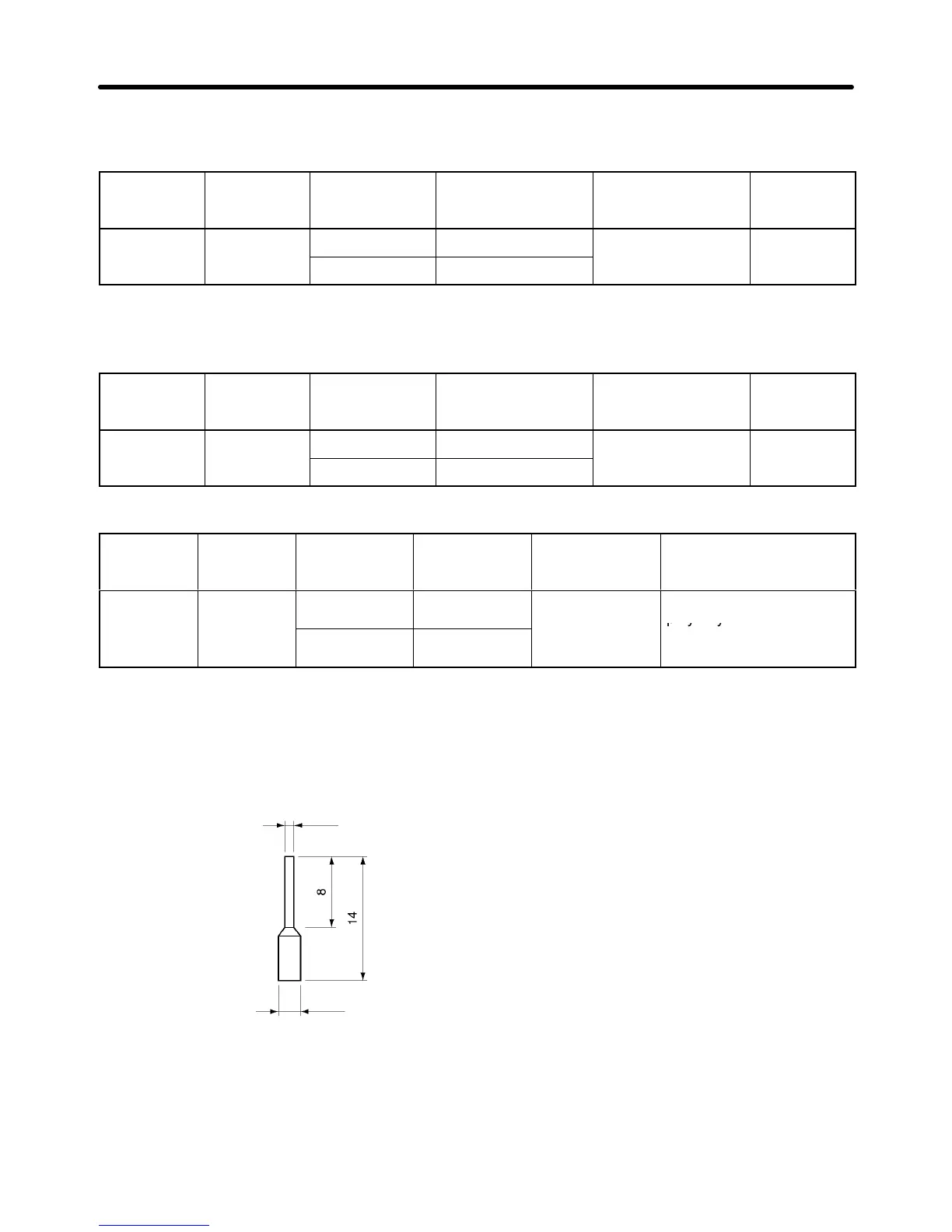
D Solderless Terminals for Control Circuit Terminals
The use of solderless terminals for the control circuit terminals is recommended because solderless
terminals are easy to connect securely.
Note When using the following solderless terminal, make sure that the wire size is 0.5 mm
2
.
1.0 dia.
2.6 dia.
Model: Phoenix Contact’s A1 0.5-8 WH
(Size: mm)
D Wiring Method
1. Loosen the terminal screws with a thin-slotted screwdriver.
2. Insert the wires from underneath the terminal block
3. Tighten the terminal screws firmly to a torque of 0.5 NSm.
Design Chapter 2

 Loading...


