7-33
7-9-2 Wiring the Communications Line
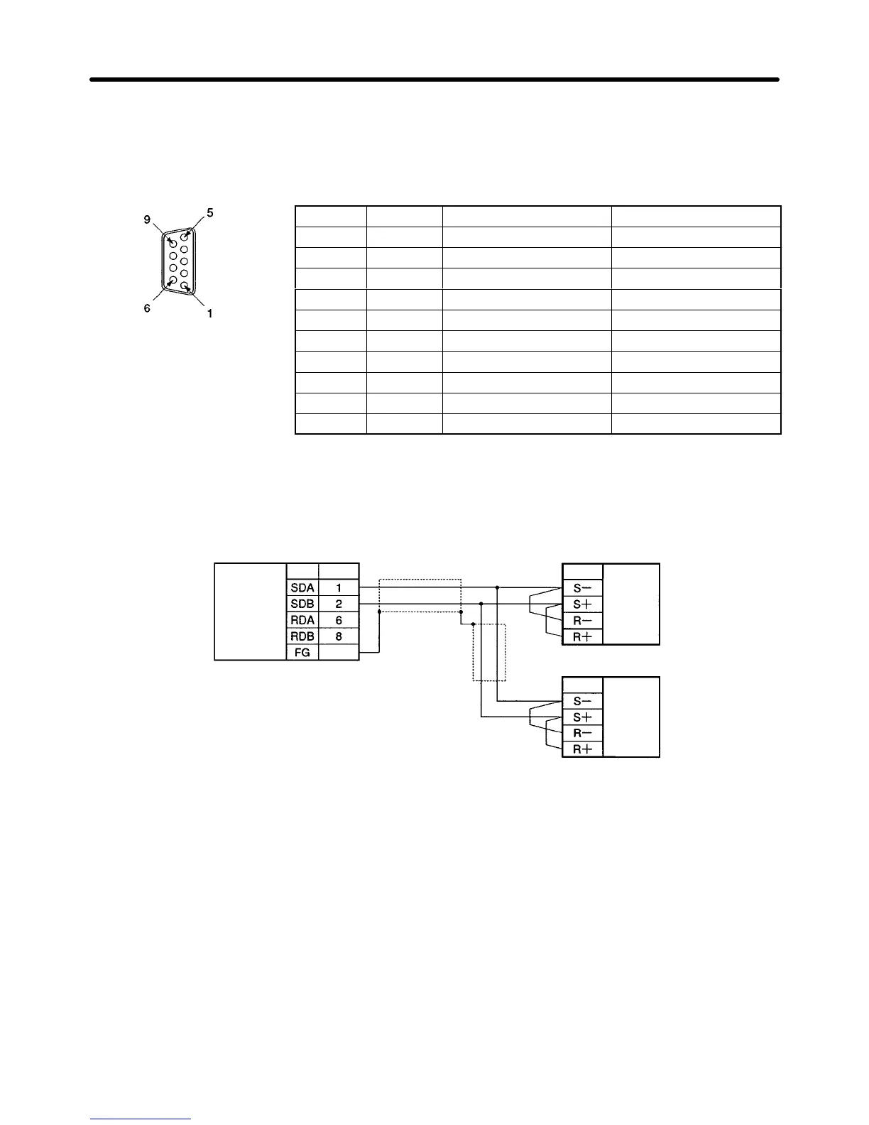
H Connector Pin Arrangements of CS1W-SCB41(-V1) and
C200HW-COM06-EV1
Pin No. Code Signal name I/O
1 SDA Send data (–) Output
2 SDB Send data (+) Output
3 NC --- ---
4 NC --- ---
5 NC --- ---
6 RDA Recv data (–) Input
7 NC --- ---
8 RDB Recv data (+) Input
9 NC --- ---
Frame FG FG ---
H Standard Connection Diagram
D RS-485 (2-wire)
Communications Board
RS-422
/485
Interface
Code Pin No.
Frame
9-pin, D-sub connector
(Cable side: Male)
3G3MV
Code
3G3MV
Code
Control
circuit ter-
minal block
(commu-
nications
terminals)
Control
circuit ter-
minal block
(commu-
nications
terminals)
Shielded line
Note Be sure to set the terminal resistance of only the Inverter at each end to ON and that any other
Inverter to OFF. Refer to page 2-18, Selecting RS-422/485 Termination Resistance for details.
Communications Chapter 7

 Loading...


