2-33
Reactor Effects
Harmonics are effectively suppressed when the DC reactor is used with the AC reactor as shown in the
following table.
Harmonics
Harmonic generation rate (%)
suppression
method
5th har-
monic
7th har-
monic
11th har-
monic
13th har-
monic
17th har-
monic
19th har-
monic
23rd
har-
monic
25th
har-
monic
No reactor 65 41 8.5 7.7 4.3 3.1 2.6 1.8
AC reactor 38 14.5 7.4 3.4 3.2 1.9 1.7 1.3
DC reactor 30 13 8.4 5 4.7 3.2 3.0 2.2
DC and AC
reactors
28 9.1 7.2 4.1 3.2 2.4 1.6 1.4
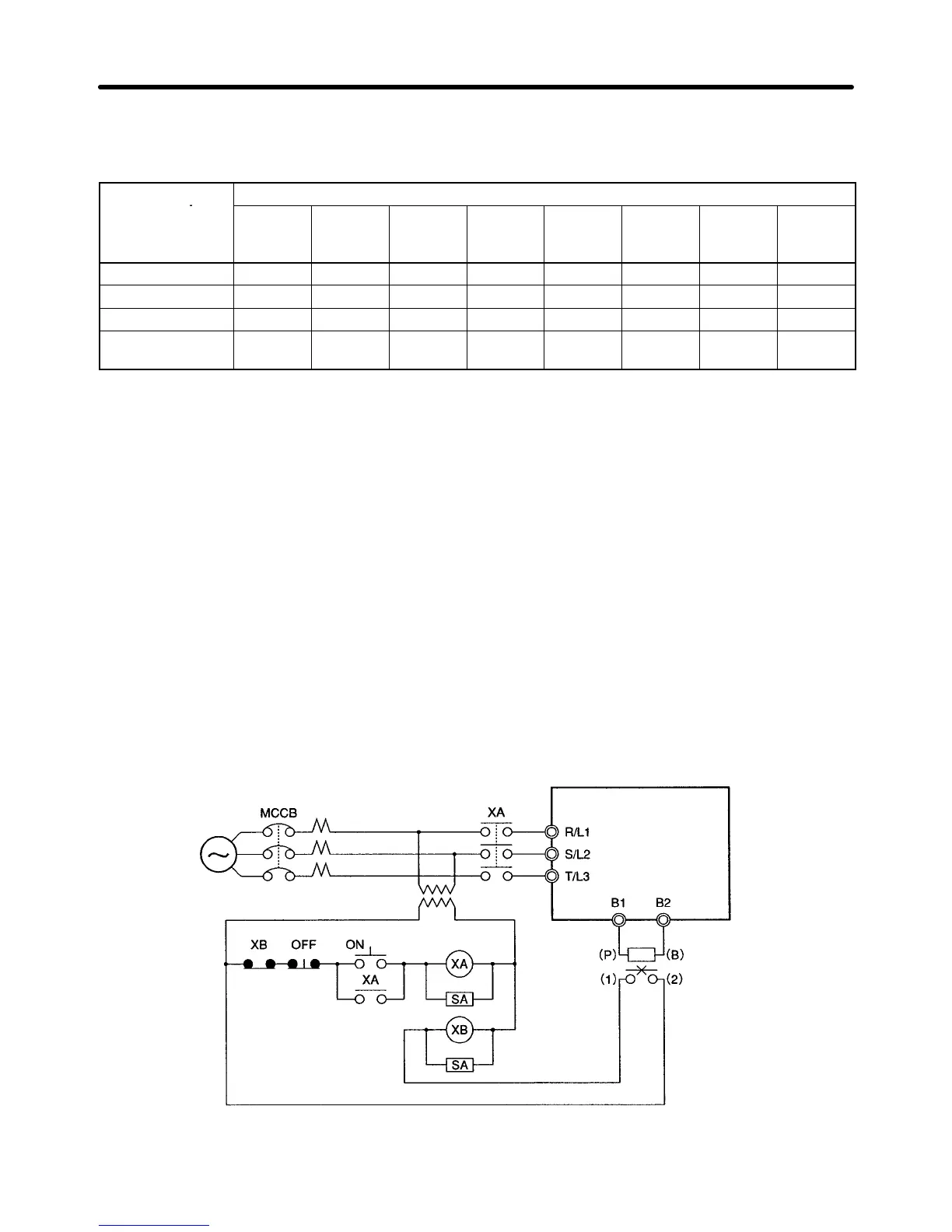
H Connecting the Braking Resistor and Braking Resistor Unit
When running a load with a large inertia or a vertical axis, regeneration energy will return to the Inverter.
If OV (overvoltage) is generated during deceleration, this indicates that the regeneration energy is
exceeding the capacity of the Inverter. In this case, use a Braking Resistor or a Braking Resistor Unit.
• Connect the Braking Resistor as shown in the following diagram.
Note 1. When using a Braking Resistor, install a thermal relay to monitor the temperature of the resis-
tor.
Note 2. When using a Braking Resistor or a Braking Resistor Unit, be sure to include a sequence
whereby the power supply for the Inverter will be turned OFF in the case of abnormal over-
heating. Not doing so may result in burning.
S Braking Resistor: Use the output of the thermal relay used to monitor the temperature of the ther-
mometer.
S Braking Resistor Unit: Use the error contact output of the Braking Resistor Unit.
• When using a Braking Resistor, and Braking Resistor Unit be sure to set n092 (deceleration stall pre-
vention selection) to “1” (without deceleration stall prevention).
3-phase, 400 V AC (single-phase
200 V AC/3-phase 200 V AC)
Power
supply
Inverter
Braking
Resistor/Braking
Resistor Unit
Contact points for thermal trip of Braking Resistor
Unit or external thermal relay
Design Chapter 2

 Loading...


