5-17
D Setting the Filter Time Constant for Multi-function Analog Voltage/Current Input
(n070 and n073)
• These parameters can be used to set a primary-delay digital filter for multi-function analog voltage
input. For voltage inputs, set the multi-function analog voltage input filter time constant (n070). For
current inputs, set the multi-function analog current input filter time constant (n073).
• These parameter settings are effective for smooth operation of the Inverter if the analog input signal
changes too rapidly or the signal is interfered with by noise.
• The larger the set value is, the lower the response will be.
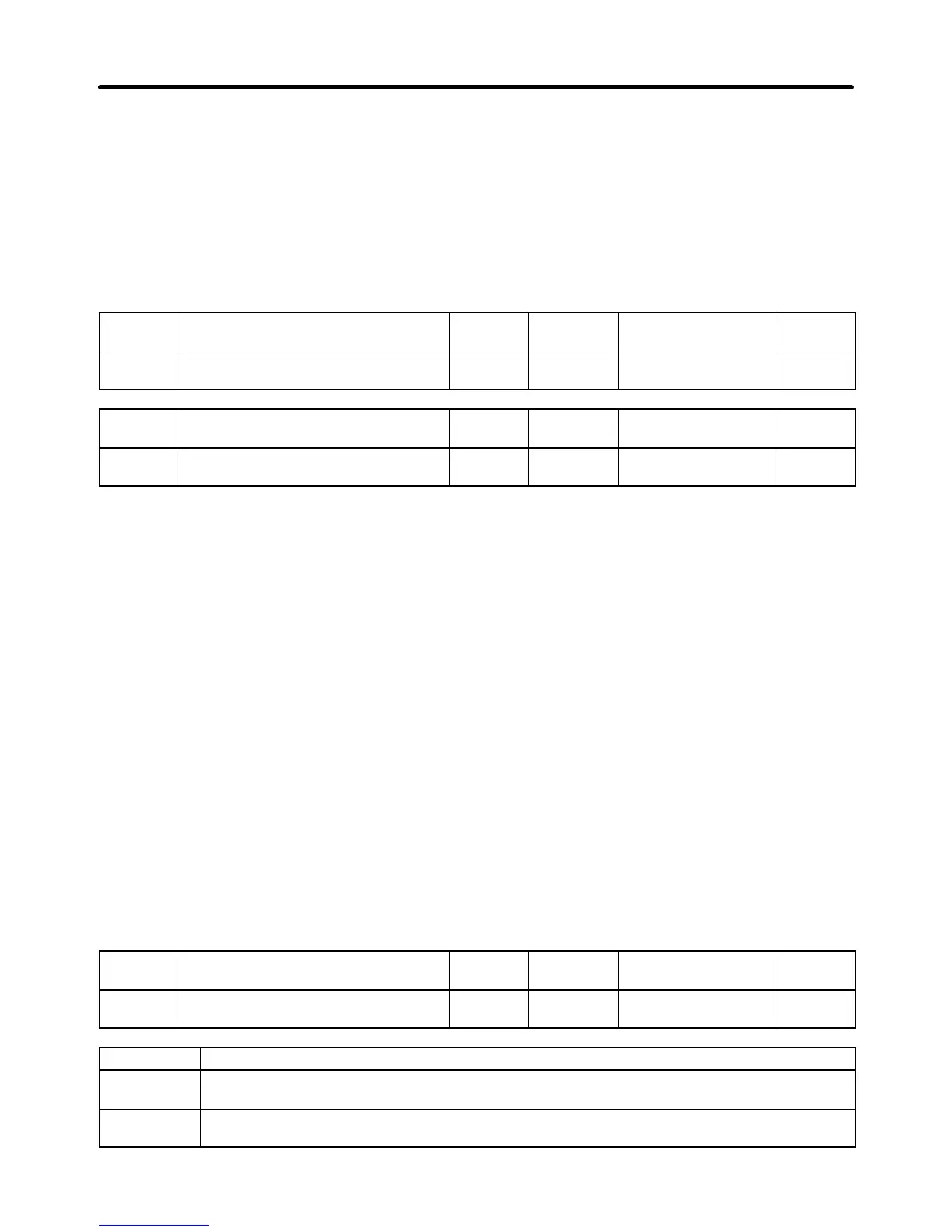
n070
Multi-function Analog Voltage
Input Filter Time Constant
Register 0146 Hex Changes during
operation
Yes
Setting
range
0.00 to 2.00 (s) Unit of
setting
0.01 s Default setting 0.10
n073
Multi-function Analog Current
Input Filter Time Constant
Register 0149 Hex Changes during
operation
Yes
Setting
range
0.00 to 2.00 (s) Unit of
setting
0.01 s Default setting 0.10
H Frequency Reference Loss Detection (n064)
This function is provided for 5.5- and 7.5-kW Inverters only. If the frequency reference from the control
circuit drops by more than 90% within 400 ms, this function detects it and determines that the reference
has been lost (e.g., from some cause such as disconnected wiring).
• When operating in remote mode, the setting for the frequency reference loss detection function is en-
abled when either an analog reference or a pulse train reference is selected for n004 (frequency refer-
ence selection).
Note 1. If “frequence reference agree” (set value: 2) is preset for multi-function outputs 1 to 3 (n057 to
n059), the frequency reference loss status can be checked. When using this output, imple-
ment external error processing.
Note 2. When the frequency reference loss detection is enabled and a loss is detected, operation will
continue at 80% of the frequency reference prior to the loss.
Note 3. If the frequency reference is restored during a frequency reference loss, and the frequency
returned to at least the level of the continuing operation, the frequency reference loss detec-
tion will be cleared and the Inverter will return to normal operation.
Note 4. Frequency reference loss detection does not operate for multi-function analog inputs.
n064
Frequency Reference Loss
Detection
Register 0140 Hex Changes during
operation
No
Setting
range
0, 1 Unit of
setting
1 Default setting 0
Value Description
0 Loss detection disabled. (Operation according to frequency reference; frequency reference
loss detection disabled.)
1 Loss detection enabled. (After loss detection, operation continues at 80% of the frequency
reference prior to the loss; frequency reference loss detection enabled.)
Basic Operation
Chapter 5

 Loading...


