5-34
H Operation in 3-wire Sequence (n052 = 0)
• The Inverter operates in 3-wire sequence by setting n052 for multi-function input 3 to 0.
• Only n052 can be set to 0 (3-wire sequence). By making this setting, the set values in n050 and n051
are ignored and the following settings are forcibly made.
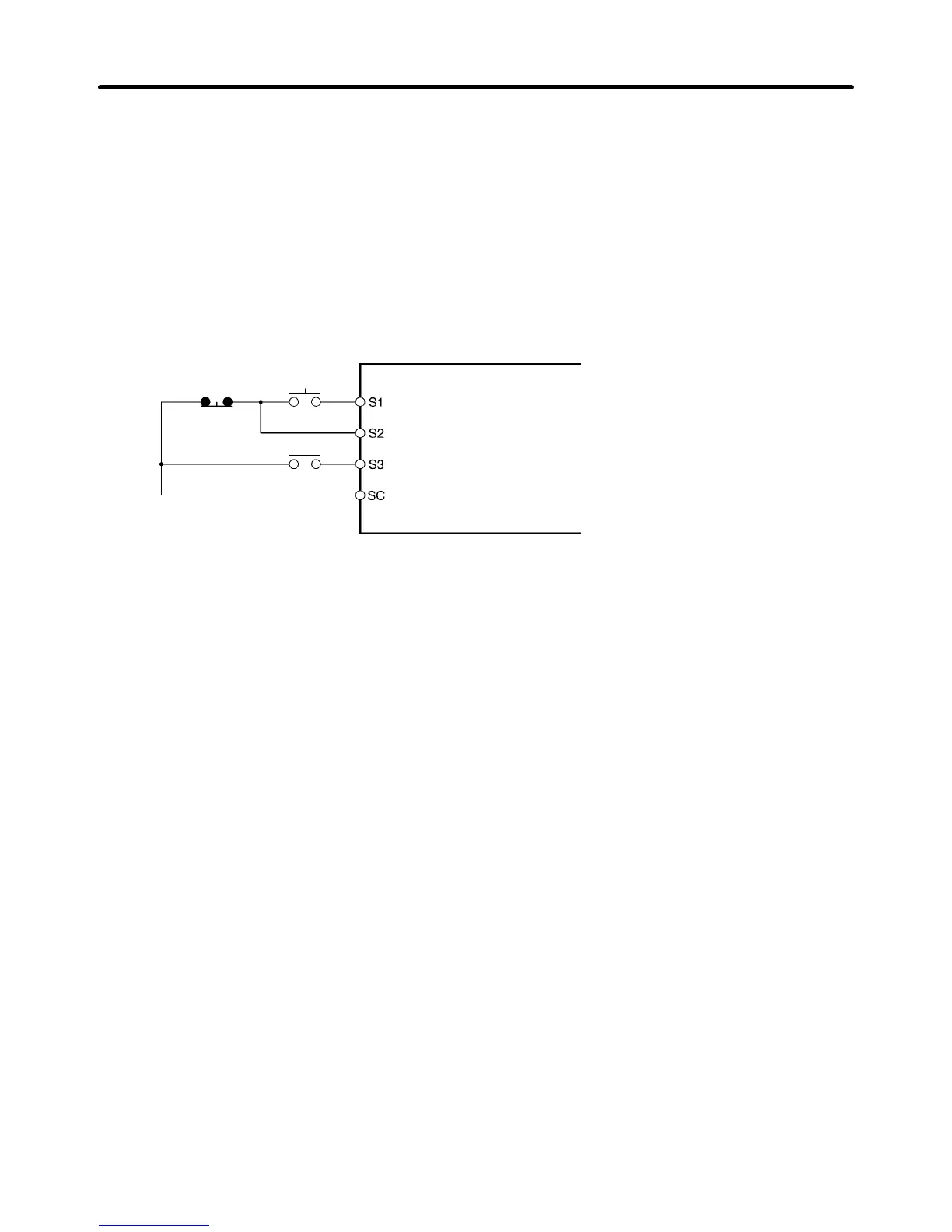
S1: RUN input (RUN when ON)
S2: STOP input (STOP when OFF)
S3: Forward/Reverse rotation command (OFF: Forward; ON: Reverse)
• The following diagram shows a wiring example of the terminals in 3-wire sequence.
Stop
switch
(NC)
RUN
switch
(NO)
Direction switch
RUN input (Operates with the RUN switch closed)
Stop input (Stops with the stop switch opened)
Forward/Reverse rotation command (Forward with the Direction
switch opened, Reverse with the Direction switch closed)
Sequence input common
Note Set parameter n052 (terminal S3) to 0 if a 3-wire sequence is set.
H External Base Block Command (Set Value: 12, 13)
When an SPST-NO (set value: 12) or SPST-NC (set value: 13) input is received, Inverter outputs are
shut OFF. Use these inputs in the following cases to stop Inverter outputs.
• For switching the motor to free running status when applying an external brake.
• For stopping Inverter outputs before disconnecting motor wiring when changing the motor from an
Inverter to a commercial power supply.
Note The external base block only shuts Off the Inverter’s output frequency, and the Inverter’s internal
frequency continues to be calculated as usual. Therefore, if the external base block is cleared
when the frequency is not zero, the frequency calculated at that point will be output. Because of
this, if the baseblock is cleared during deceleration while the motor is free running, a large dis-
crepancy between the motor speed at that moment and the Inverter output frequency may result
in a main circuit overvoltage (OV) or overcurrent (OC).
Basic Operation
Chapter 5

 Loading...


