6-20
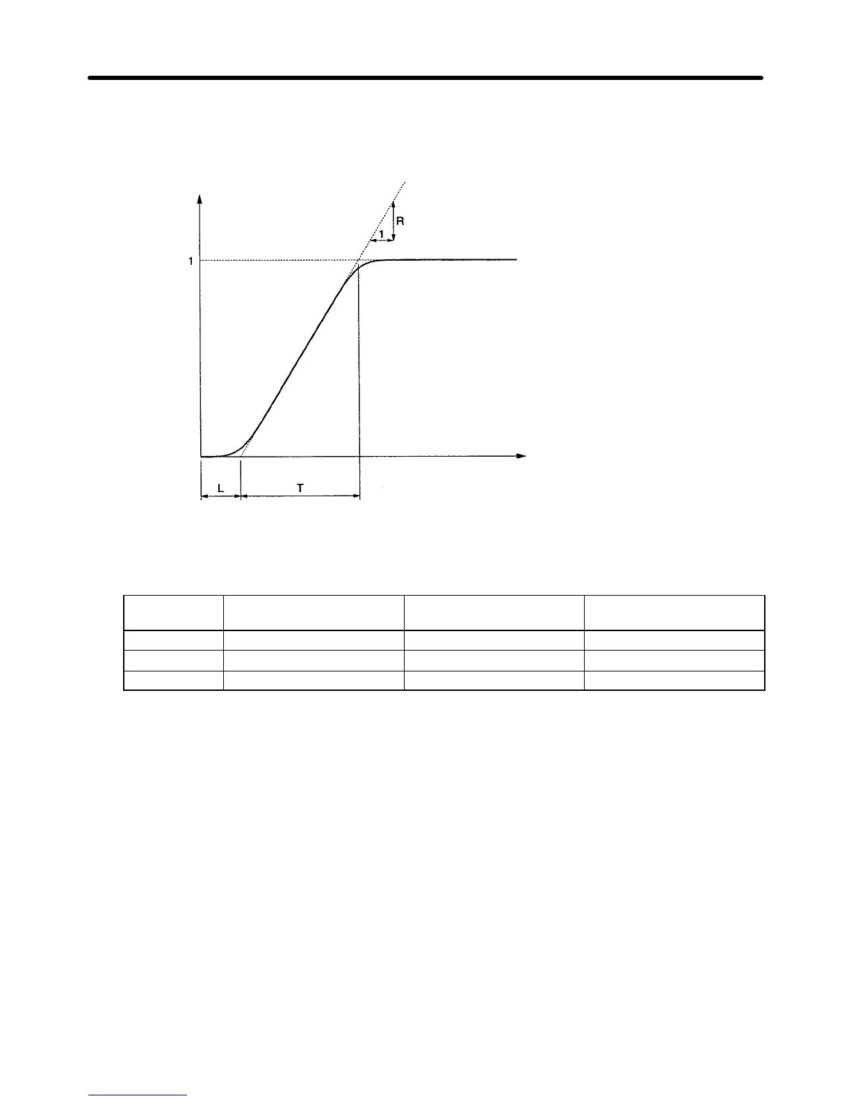
S Measurement of T
Measure the required time (seconds) between the point of intersection of the tangent line and time
axis and the point of intersection of the tangent line and set point line.
Response
Target value
Time
S PID Parameter
The following PID parameters are calculated from the R, L, and T of intersection of the tangent line
and set point line as general rules.
Control Proportional (P) gain
(n130)
Integral (I) time (n131) Derivative (D) time (n132)
P control 0.3/RL --- ---
PI control 0.35/RL 1.2T ---
PID control 0.6/RL T 0.5L
Note 1. Obtain PID parameter values from the above method, set the PID parameters, and tune in the
PID parameter values precisely.
Note 2. PID parameter values obtained from the above method may not be optimum if the friction fac-
tor of the mechanical system is large or the rigidity of the mechanical system is low.
H Manual PID Adjustments
• Perform the following procedure to adjust the PID parameter values of the Inverter performing PID
control by monitoring the response waveform.
1. Connect the load in the same way as the connection of the load to the Inverter in normal operation.
2. Set n128 so that the Inverter will perform PID control.
3. Increase the proportional (P) gain in n130 within a range causing no vibration.
4. Increase the integral (I) time in n131 within a range causing no vibration.
5. Increase the derivative (D) time in n132 within a range causing no vibration.
Advanced Operation Chapter 6

 Loading...


