6-24
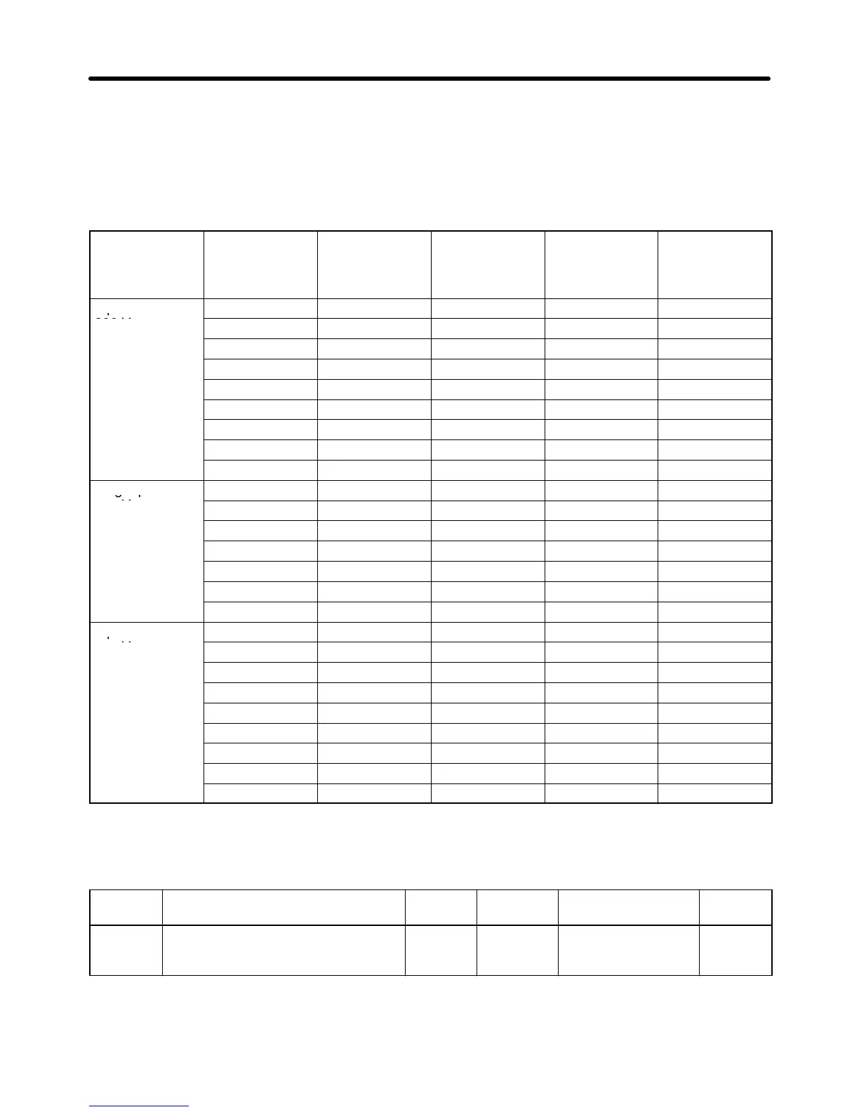
• The Inverter cannot maintain rated output current with the carrier frequency set to a value higher than
the default one.
The following table shows the default settings and the reduced rated output currents resulting from a
higher setting for the carrier frequency for each Inverter model.
When the carrier frequency is set to a higher value than the default setting, use the Inverter at a current
less than the reduced rated output current.
Voltage Model 3G3MV- Default setting Rated output
current (A)
Set to 3
Reduced rated
output current
(A)
Set to 4
Reduced rated
output current
(A)
3-phase
A2001 4 (10 kHz) 0.8 ← ←
200 V
A2002 4 (10 kHz) 1.6 ← ←
A2004 4 (10 kHz) 3.0 ← ←
A2007 4 (10 kHz) 5.0 ← ←
A2015 3 (7.5 kHz) 8.0 ← 7.0
A2022 3 (7.5 kHz) 11.0 ← 10.0
A2037 3 (7.5 kHz) 17.5 ← 16.5
A2055 3 (7.5 kHz) 25.0 ← 23.0
A2075 3 (7.5 kHz) 33.0 ← 30.0
Single-phase
AB001 4 (10 kHz) 0.8 ← ←
200 V
AB002 4 (10 kHz) 1.6 ← ←
AB004 4 (10 kHz) 3.0 ← ←
AB007 4 (10 kHz) 5.0 ← ←
AB015 3 (7.5 kHz) 8.0 ← 7.0
AB022 3 (7.5 kHz) 11.0 ← 10.0
AB037 3 (7.5 kHz) 17.5 ← 16.5
3-phase
A4002 3 (7.5 kHz) 1.2 ← 1.0
400 V
A4004 3 (7.5 kHz) 1.8 ← 1.6
A4007 3 (7.5 kHz) 3.4 ← 3.0
A4015 3 (7.5 kHz) 4.8 ← 4.0
A4022 3 (7.5 kHz) 5.5 ← 4.8
A4030 3 (7.5 kHz) 7.2 ← 6.3
A4037 3 (7.5 kHz) 8.6 ← 8.1
A4055 3 (7.5 kHz) 14.8 ← 14.8 (See note.)
A4075 3 (7.5 kHz) 18.0 ← 17.0
Note The rated output current can be output without reduction.
n175
Low Carrier Frequency at Low
Speed
Register 01AF Hex Changes during
operation
No
Setting
range
0, 1 Unit of
setting
1 Default setting 0
(See
note.)
Note For 5.5- and 7.5-kW Inverters, the default setting is “1” (enable).
Advanced Operation Chapter 6
 Loading...


