7-35
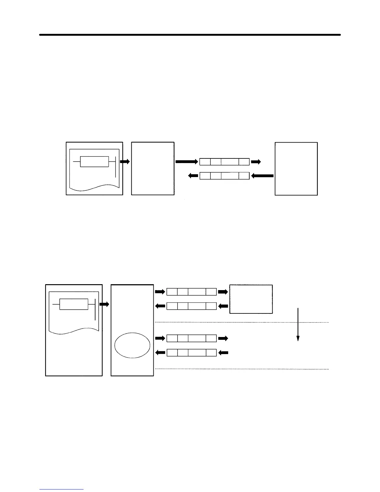
D Creating a Message
• The message can be created according to the communications specifications of the general-purpose
peripheral device (Inverter) as a counterpart.
• A DSR message can include variables to set data in the I/O memory (such as data memory) of the
CPU Unit or write response data to the I/O memory.
• Each component of a message is in the memory of the Communications Board. Therefore, the CPU
Unit can just execute the PMCR instruction to send or receive the data. Therefore, there is no need to
write ladder programs for the communications protocol.
CPU Unit
PMCR
instruction
Communications
Board
DSR message
Reception
Response
Send
3G3MV
D Step to Send and Receive Messages
• Sending and receiving messages as a single step includes step-type commands, such as Send, Recv,
Send & Recv, and Wait commands.
• The step can be finished or switched to another step according to the result of the step.
CPU Unit
PMCR
instruction
Communications
Board
Next process
according to
the result.
3G3MV
Step 0
To step n according to the
result.
H Configuration of Protocol Macro Function
• The protocol consists of one or more sequences.
A sequence is an independent set of actions to perform together with a general-purpose peripheral
device, such as an Inverter. The RUN command and the frequency reference are given to the Inverter
and the status of the Inverter is read in a single sequence, for example.
• A sequence consists of one or more steps.
Communications Chapter 7

 Loading...


