7-45
• DSR Message to Read the Inverter Status
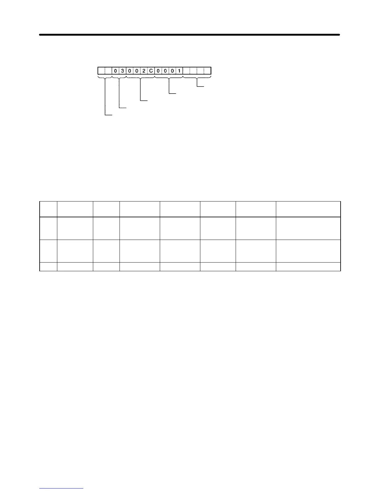
The DSR message to read the Inverter status from register 002C Hex consists of the following items.
CRC-16 check (Set with <c>)
Number of read data registers: 1
Read start register number (Inverter status: 002C)
Function code (Read 03)
Slave address (Set with <a>)
Set data: <a> + [03] + [00] + [2C] + [00] + [01] + <c>
Set the address data, constant data, and check code data.
H Recv Message Detail Settings
1. With the left button of the mouse, click on Receive Message List. Then click on a blank space with
the right button of the mouse.
2. Select Create Receive Message.
The following table will appear. Set the Receive message in the table.
* Message Header
<h>
Terminator
<t>
Check code
<c>
Length
<l>
Address
<a>
Data
→j
Input
response
~
CRC-16
(65535)
(2Byte BIN)
~
(R (3N+2),
1)
<a> + [10] + [00] +
[01] + [00] + [02] +
<c>
→j
Read
response
~
CRC-16
(65535)
(2Byte BIN)
(0) (1Byte
BIN)
~
(R (3N+2),
1)
<a> + [03] + <I> + (W
(1N + 1), 2) + <c>
→j
Message
The label (name) of the response. Input an appropriate, easy-to-distinguish name.
Note Set the label in the Recv message box in the table shown under Creating a Step.
Header <h>
Terminator <t>
Set the header and terminator.
Note No header or terminator is used for communications with the 3G3MV. Therefore, set both to
None.
Check Code <c>
Set the check code.
Note The CRC-16 check code is used for communications with the 3G3MV. Select the CRC-16 check
code and set the initial value to 65535.
Select Reverse for the conversion method. Then select BIN as the data type.
Length <l>
Set the length of the data.
Note All communications with the 3G3MV are performed in byte units. Select 1 Byte and BIN. Select
No for reading data because there is no data to be read.
Communications Chapter 7

 Loading...


