3-15
H Copying the Data in the EEPROM of the Digital Operator to another
Inverter (CPy)
• To copy the parameter set values to another Inverter from the EEPROM of the Digital Operator, set
n176 for parameter copy function selection to CPy.
• When the parameter set values have been read, turn OFF the Inverter and remove the Digital Opera-
tor. Refer to 2-1-3 Removing and Mounting the Covers for details.
• Mount the Digital Operator to the Inverter to which the parameters are copied. Then turn ON the
Inverter.
• Check that n001 for parameter write-prohibit selection/parameter initialization is set to 4 in the Inverter
(i.e., values can be set in n001 through n179). If n001 is not set to 4, take the steps described above
and set n001 to 4.
Note The above procedure is possible provided that the Inverters are the same in power supply specifi-
cation and control mode (i.e., V/f or vector control).
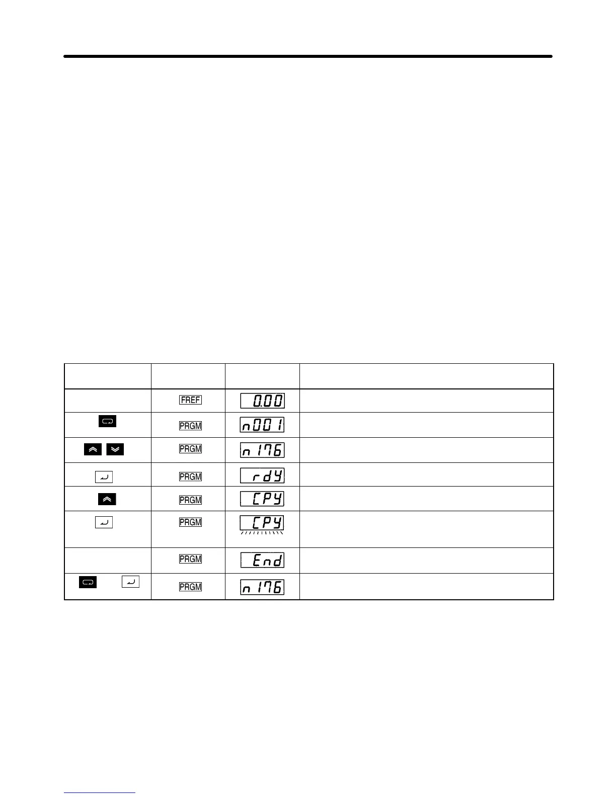
D Procedure to Read the Parameter Set Values
Key sequence Indicator Display
example
Explanation
Power ON
Press the Mode Key repeatedly until the PRGM
indicator is lit.
Use the Increment or Decrement Key to display
“n176.”
Press the Enter Key. Then “rdy” will be displayed.
Use the Increment Key to display “CPy.”
Press the Enter Key so that the parameter set values
in the EEPROM of the Digital Operator will be copied
to the Inverter, during which the display flashes.
Completes When the set values have been all copied, “End” will
be displayed.
or
Press the Mode or Enter Key. The parameter number
(n176) will be displayed again.
Note 1. Check and verify the set ranges and set values of the parameters written to the Inverter. If any
error is found as a result, all the parameter set values will be prohibited and the previous val-
ues will be reset.
If a set range error results, the corresponding parameter number will flash. In the case of a
verification error, “oPj” (j is a figure) will flash.
Note 2. The following parameter set values or output frequency on hold cannot be copied.
n176: Parameter copy function selection n178: Error log
n177: Parameter read-prohibit selection n179: Software version
Preparing for Operation and Monitoring Chapter 3

 Loading...


