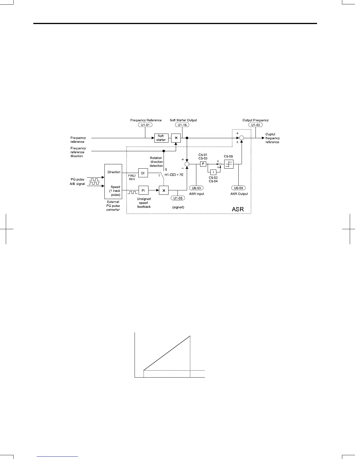
The pulse input provides one track only and can not detect the direction of motor rotation. A separate motor speed direction
signal must therefore be input to the ASR by:
1. Using a Digital Input
This method is automatically enabled when a digital input is programmed for “Forward/Reverse direction” (H1-=
7E). If the input is closed, the drive assumes reverse rotation. If open, then the drive assumes that the motor is rotating
forwards.
When a 2 track encoder is used, an external unit that converts the 2 tracks into 1 track and a digital direction signal can
be used.
2. Using the Frequency Reference Direction
When no digital input is set for “Forward/Reverse direction” (H1-≠ 7E), ASR uses the direction of the frequency
reference.
Figure 5.27 illustrates the ASR function when using V/f with Simple Speed Feedback.
Motor speed
Figure 5.27 Speed Control with ASR in V/f with Simple Speed Feedback
To activate V/f Control with PG feedback:
1. Set the drive to V/f Control (A1-02 = 0).
2. Connect the motor speed pulse signal to the pulse input RP, set H6-01 = 3, and set the pulse signal frequency that is
equal to the maximum speed to H6-02 (pulse input scaling). Make sure the pulse input bias (H6-04) is 0% and the gain
(H6-03) is 100%.
3.
Decide the signal used for detecting the direction. If a digital input is used set H1- = 7F.
4. Use the ASR gain and integral time parameters described below for adjusting the ASR responsiveness.
Note: 1. C5 parameters will appear only when using V/f Control (A1-02 = 0) and when the pulse input RP function is set for PG feedback in
V/f Control (H6-01 = 3).
2. V/f Control with PG feedback can be used for motor 1 only.
ASR Tuning Parameters
ASR provides two sets of gain and integral time. Set 1 is active at the maximum output frequency, set 2 is active at the
minimum output frequency. The settings are changed linearly depending on the output frequency as shown in Figure
5.28.
0
P = C5-03
I = C5-04
P = C5-01
I = C5-02
P gain and I time
Motor Speed
E1-04
Maximum
Output
Frequency
E1-09
Minimum
Output
Frequency
Figure 5.28 Adjusting ASR Proportional Gain and Integral Time
n
C5-01/02: ASR Proportional Gain/Integral Time 1
These parameters determine the responsiveness of ASR at maximum output frequency.
5.3
C: Tuning
130
SIEP C710606 20 OYMC AC Drive - V1000 User Manual
7/16/2008-13:23
 Loading...


