Setting 0: Lower Limit is Determined by d2-02 or Analog Input
The lower frequency reference limit is determined by the higher value of both, parameter d2-02 or an analog input that is
programmed for “Frequency Bias” (H3-02/10 = 0).
Note:
If the external reference change over function (H1- = 2) used to switch between Up/Down function and analog input as reference
source, the analog value would become the lower reference limit when the Up/Down reference is active. Change d4-10 to 1 to make the
Up/Down function independent of the analog input value.
Setting 1: Lower Limit is Determined by Parameter d2-02
Only parameter d2-02 sets the lower frequency reference limit.
n
d4-11: Bi-Directional Output Selection
Selects if the frequency reference or PID output value is converted into bi-directional internal frequency reference. Refer
also to the PID block diagram in Figure 5.18 to see how bi-directional output works.
Note:
When used in combination with PID control, the bi-directional output function can be enabled or disabled using a digital input (H1-
= 7F).
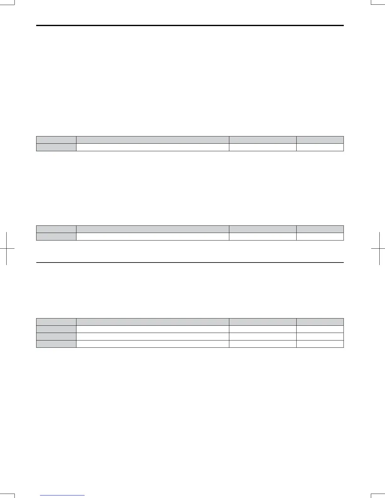
No. Parameter Name Setting Range Default
d4-11 Bi-Directional Output Selection 0 or 1 0
Setting 0: No Conversion
The frequency reference or PID output value is used as it is without being converted. The drive will operate in the direction
selected from 0 to 100% of the maximum output frequency.
Setting 1: Bi-Directional Output Conversion
When the frequency reference or PID output is below 50%, the drive reverses the selected direction. When it is above 50%
the drive works in the selected direction.
n
d4-12: Stop Position Gain
Sets the gain for adjusting the stopping accuracy when simple positioning is selected as the stopping method (b1-03 = 9).
No. Parameter Name Setting Range Default
d4-12 Stop Position Gain 0.50 to 2.55 1.00
Increase the value if the motor stops before the desired stop position is reached. Decrease it if the motor stops too late.
Refer to b1-03: Stopping Method Selection on page 105 for details on simple positioning.
u
d7: Offset Frequencies
n
d7-01 to d7-03: Offset Frequency 1 to 3
Three different offset values can be added to the frequency reference. They can be selected using digital inputs programmed
for Offset frequency 1, 2 and 3 (H1- = 44, 45, 46). The selected offset values are added if two or all three inputs are
closed at the same time.
Note:
This function can be used to replace the “Trim Control” function (H1- = 1C/1D) of earlier OYMC drives.
No. Parameter Name Setting Range Default
d7-01 Offset Frequency 1 -100.0 to 100.0% 0%
d7-02 Offset Frequency 2 -100.0 to 100.0% 0%
d7-03 Offset Frequency 3 -100.0 to 100.0% 0%
Figure 5.39 illustrates the Offset Frequency Function.
5.4
d: Reference Settings
142
SIEP C710606 20 OYMC AC Drive - V1000 User Manual
7/16/2008-13:23