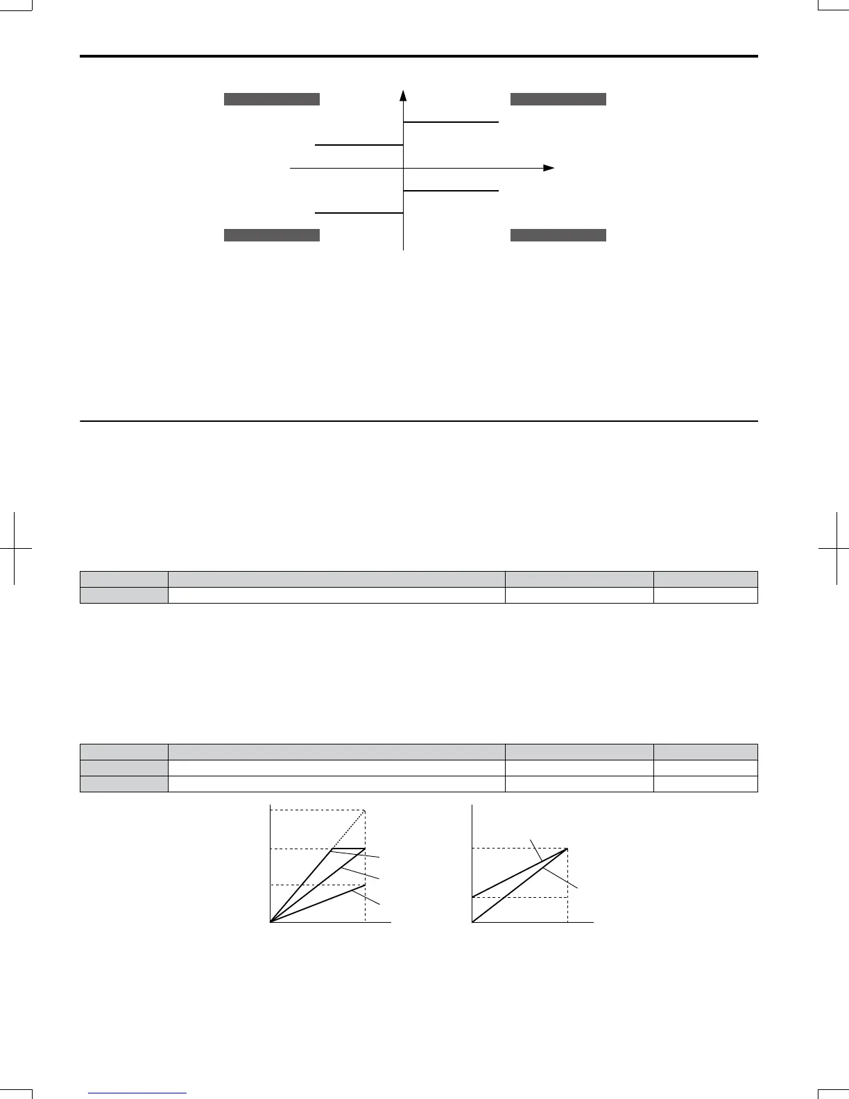
positive torque reference
negative torque reference
10: Positive Torque Limit
12: Regenerative Torque Limit
15: Torque Limit
Parameter L7-04
REV motor rotation
11: Negative Torque Limit
15: Torque Limit
Parameter L7-03
10: Positive Torque Limit
15: Torque Limit
Parameter L7-01
FWD motor rotation
11: Negative Torque Limit
12: Regenerative Torque Limit
15: Torque Limit
Parameter L7-02
quadrant 2
quadrant 3
quadrant 1
quadrant 4
REV run regenerative
REV run motoring
FWD run motoring
FWD run regenerative
Figure 5.71 Analog Input Torque Limits
Setting 16: Differential PID Feedback
If an analog value is set for this function, the PID controller is set for differential feedback. The subtraction of the PID
feedback input value and the differential feedback input value builds the feedback value that is used to calculate the PID
input. Refer to PID Feedback Input Methods on page 116.
Setting 30/31: FBDs Analog Input 1/2
These settings are for analog output functions used by FBDs. Normally there is no need to change or apply these settings.
u
H4: Multi-Function Analog Output Terminals
These parameters assign a function to analog output terminal AM for monitoring a specific aspect of drive performance.
n
H4-01: Multi-Function Analog Terminal AM Monitor Selection
Sets the desired drive monitor parameter U- to output as an analog value via terminal AM. Refer to U:
Monitors on page 332 for a list of all monitors. The “Analog Output Level” columns indicates if a monitor can be applied
for analog output.
Example: Enter “103” for U1-03.
No. Name Setting Range Default
H4-01 Multi-Function Analog 1 (Terminal AM Monitor Selection) 000 to 999 102
A setting of 031 or 000 applies no drive monitor to the analog output. With this setting the terminal AM output level can
be set by a PLC via a communication option or MEMOBUS/Modbus communications (through mode).
n
H4-02/H4-03: Multi-Function Analog Output Terminal AM Gain/Bias
Parameter H4-02 sets the output voltage that is equal to 100% of the monitor value. Parameter H4-03 sets the output voltage
equal to 0% of the monitor value.
Both values are set as a percentage of 10 V. The minimum output voltage for terminal AM is 0 V, the maximum is 10
Vdc. Figure 5.72 illustrates the function of the gain and bias settings.
No. Name Setting Range Default
H4-02 Multi-Function Analog Output Terminal AM Gain -999.9 to 999.9% 100.0%
H4-03 Multi-Function Analog Output Terminal AM Bias -999.9 to 999.9% 0.0%
0 V
3 V
10 V
Bias 30%
Gain 100%
Bias 0%
Gain 100%
100%
Monitor value
0%
Gain 50%
Bias 0%
Terminal AM
output
voltage
0 V
5 V
10 V
Gain 150%
Bias 0%
Gain 100%
Bias 0%
100%
Monitor value
0%
Terminal AM
output
voltage
Figure 5.72 Analog Output Gain/Bias Setting
5.7 H: Terminal Functions
182
SIEP C710606 20 OYMC AC Drive - V1000 User Manual
7/16/2008-13:23