7.2 Inspection
Power electronics have limited life and may exhibit changed characteristics or performance deterioration after years of
use under normal conditions. To help avoid such problems, it is important to perform preventive maintenance and periodic
inspection on the drive.
Drives contain a variety of power electronics such as power transistors, semiconductors, capacitors, resistors, fans, and
relays. The electronics in the drive serve a critical role in maintaining proper motor control.
Follow the inspection lists provided in this chapter as a part of a regular maintenance program.
Note: The drive will require more frequent inspection if it is placed in harsh environments, such as:
• High ambient temperatures
• Frequent starting and stopping
• Fluctuations in the AC supply or load
• Excessive vibrations or shock loading
• Dust, metal dust, salt, sulfuric acid, chlorine atmospheres
• Poor storage conditions.
Perform the first equipment inspection 3 months after installation.
u
Recommended Daily Inspection
Table 7.1 outlines the recommended daily inspection for OYMC drives. Check the following items on a daily basis to
avoid premature deterioration in performance or product failure. Copy this checklist and mark the “Checked” column after
each inspection.
WARNING! Electrical Shock Hazard. Do not connect or disconnect wiring while the power is on. Failure to comply can result in serious
personal injury. Before servicing the drive, disconnect all power to the equipment. The internal capacitor remains charged even after
the power supply is turned off. The charge indicator LED will extinguish when the DC bus voltage is below 50 Vdc. To prevent electric
shock, wait at least five minutes after all indicators are OFF and measure the DC bus voltage level to confirm safe level.
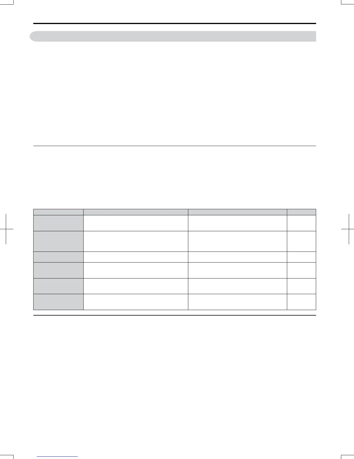
Table 7.1 General Recommended Daily Inspection Checklist
Inspection Category Inspection Points Corrective Action Checked
Motor
• Inspect for abnormal oscillation or noise coming
from the motor.
• Check the load coupling.
• Measure motor vibration.
• Tighten all loose components.
Cooling
• Inspect for abnormal heat generated from the drive
or motor and visible discoloration.
• Check for excessive load.
• Loose connections
• Check for dirty heatsink or motor.
• Ambient temperature
Cooling Fan • Inspect drive cooling fan operation.
• Check for clogged or dirty fan.
• Check fan operation drive parameter.
Environment
• Verify the drive environment complies with the
specifications listed in the Installation section of this
manual.
• Eliminate the source of contaminants or correct
poor environment.
Load
• The drive output current should not be higher than
the motor or drive rating for an extended period of
time.
• Check for excessive load.
• Check the motor parameter settings of the drive.
Power Supply Voltage • Check main power supply and control voltages.
• Correct the voltage or power supply to within
nameplate specifications.
• Verify all main circuit phases.
u
Recommended Periodic Inspection
Table 7.2 outlines the recommended periodic inspections for OYMC drive installations. Periodic inspections should
generally be checked every 3-6 months; however, the drive may require more frequent inspection due to poor environments
or rigorous use. Operating and environmental conditions, along with experience in each application, will determine the
actual inspection frequency for each installation. Periodic inspection will help to avoid premature deterioration in
performance or product failure. Copy this checklist and mark the “Checked” column after each inspection.
n
Periodic Inspection
WARNING! Electrical Shock Hazard. Do not connect or disconnect wiring while the power is on. Failure to comply can result in serious
personal injury. Before servicing the drive, disconnect all power to the equipment. The internal capacitor remains charged even after
the power supply is turned off. The charge indicator LED will extinguish when the DC bus voltage is below 50 Vdc. To prevent electric
shock, wait at least five minutes after all indicators are OFF and measure the DC bus voltage level to confirm safe level.
7.2
Inspection
264
SIEP C710606 20 OYMC AC Drive - V1000 User Manual
7/16/2008-13:23