No. Parameter Name Default Setting
E1-03 V/f Pattern Selection 0FH
L2-01 Momentary Power Loss Operation Selection 1: Enabled
L3-04 Stall Prevention Selection during Deceleration 1: Enabled
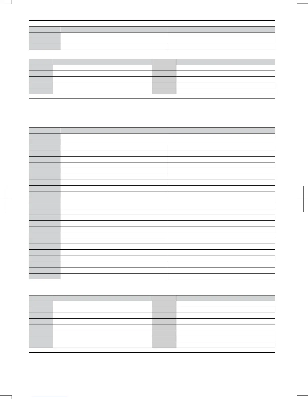
Table 4.14 Compressor: User Parameters (A2-01 to A2-16):
No. Parameter Name No. Parameter Name
b1-01 Frequency Reference Selection E1-03 V/f Pattern Selection
b1-02 Run Command Selection E1-07 Mid Output Frequency
b1-04 Reverse Operation Selection E1-08 Mid Output Frequency Voltage
C1-01 Acceleration Time 1 E2-01 Motor Rated Current
C1-02 Deceleration Time 1 − −
u
Setting 6: Hoist Application
Note: 1. Read the instructions listed on page 84 when using Hoist Application Preset
2. Perform Auto-Tuning after selecting the Hoist Application Preset.
Table 4.15 Hoist: Parameters and Settings
No. Parameter Name Default Setting
A1-02 Control Method Selection 2: Open Loop Vector Control
b1-01 Frequency Reference Selection 0: Operator
b6-01 Dwell Reference at Start 3.0 Hz
b6-02 Dwell Time at Start 0.3 s
C1-01 Acceleration Time 1 3.0 s
C1-02 Deceleration Time 1 3.0 s
C6-01 Duty Rating 0: Heavy Duty
C6-02 Carrier Frequency Selection 2: 5 kHz
d1-01 Frequency Reference 1 6.0 Hz
d1-02 Frequency Reference 2 30.0 Hz
d1-03 Frequency Reference 3 50.0 Hz
E1-03 V/f Pattern Selection 0FH
H2-02 Terminals P1 Function Selection 37: During Frequency Output
H2-03 Terminals P2 Function Selection 5: Frequency Detection 2
L2-03 Momentary Power Loss Minimum Baseblock Time 0.3 s
L3-04 Momentary Power Loss Voltage Recovery Ramp Time 0: Disabled
L4-01 Speed Agreement Detection Level 2.0 Hz
L4-02 Speed Agreement Detection Width 0.0 Hz
L6-01 Torque Detection Selection 1 8: UL3 at RUN - Fault
L6-02 Torque Detection Level 1 5%
L6-03 Torque Detection Time 1 0.5 s
L8-05 Input Phase Loss Protection Selection
1: Enabled
<1>
L8-07 Output Phase Loss Protection 1: Enabled
L8-38 Carrier Frequency Reduction 1: Enabled below 6 Hz
L8-41 Current Alarm Selection 1: Enabled (alarm is output)
<1> Disable L8-05 for single-phase models.
Table 4.16 Hoist: User Parameters (A2-01 to A2-16):
No. Parameter Name No. Parameter Name
A1-02 Control Method Selection d1-02 Frequency Reference 2
b1-01 Frequency Reference Selection d1-03 Frequency Reference 3
b6-01 Dwell Reference at Start E1-08 Mid Output Frequency Voltage
b6-02 Dwell Time at Start H2-01 Terminals MA, MB, and MC Function Selection
C1-01 Acceleration Time 1 L1-01 Motor Overload Protection Selection
C1-02 Deceleration Time 1 L4-01 Speed Agreement Detection Level
C6-02 Carrier Frequency Selection L6-02 Torque Detection Level 1
d1-01 Frequency Reference 1 L6-03 Torque Detection Time 1
u
Notes on Controlling the Brake when Using the Hoist Application Preset
Preventing Inadvertent Brake Release by Disabling Frequency Detection During a Baseblock Condition
4.6
Application Selection
84
SIEP C710606 20 OYMC AC Drive - V1000 User Manual
7/16/2008-13:23