n
L3-25: Load Inertia Ratio
Determines the ratio between the rotor inertia and the load. Set this parameter when using KEB Ride-Thru 2, Intelligent
Stall Prevention during deceleration (L3-04 = 2), or the overvoltage suppression function (L3-11 = 1).
No. Name Setting Range Default
L3-25 Load Inertia Ratio 0.0 to 1000.0 1.0
When set incorrectly, a fairly large current ripple can result during KEB Ride-Thru 2 and overvoltage suppression (L3-11
= 1) or other faults such as ov, Uv1, and oC may occur.
Parameter L3-25 can be calculated by:
L3-25 =
Machine Inertia
Motor Inertia
u
L4: Speed Agree/Frequency Reference Loss Detection
These parameters set up the speed agree and speed detection functions which can be assigned to the multi-function output
terminals.
n
L4-01/02: Speed Agreement Detection Level and Detection Width
Parameter L4-01 sets the detection level for the digital output functions “Speed Agree 1,” “User Set Speed Agree 1,”
“Frequency Detection 1,” and “Frequency Detection 2.”
Parameter L4-02 sets the hysteresis level for these functions.
No. Name Setting Range Default
L4-01 Speed Agreement Detection Level 0.0 to 400.0 Hz 0.0 Hz
L4-02 Speed Agreement Detection Width 0.0 to 20.0 Hz 2.0 Hz
Refer to H2-01 to H2-03: Terminal MA/MB/MC, P1/PC and P2/PC Function Selection on page 169, Settings 2, 3, 4,
and 5.
n
L4-03/04: Speed Agreement Detection Level and Detection Width (+/-)
Parameter L4-03 sets the detection level for the digital output functions “Speed Agree 2,” “User Set Speed Agree 2,”
“Frequency Detection 3,” and “Frequency Detection 4.”
Parameter L4-04 sets the hysteresis level for these functions.
No. Name Setting Range Default
L4-03 Speed Agreement Detection Level (+/-) 0.0 to 400.0 Hz 0.0 Hz
L4-04 Speed Agreement Detection Width (+/-) 0.0 to 20.0 Hz 2.0 Hz
Refer to H2-01 to H2-03: Terminal MA/MB/MC, P1/PC and P2/PC Function Selection on page 169, Settings 13, 14,
15, and 16.
n
L4-05: Frequency Reference Loss Detection Selection
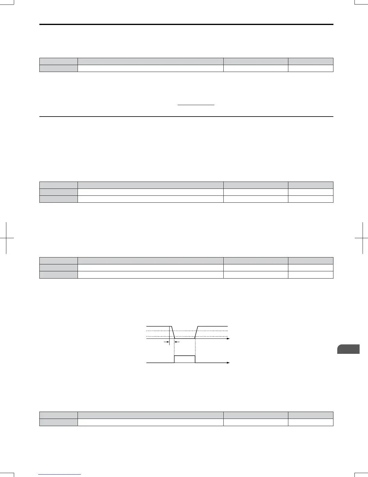
The drive can detect a loss of an analog frequency reference from input A1 or A2. Reference loss is detected when the
frequency reference value reduces for 90% within 400 ms.
100%
400ms
Analog
frequency
reference
Loss of
Reference
output
time
80%
10%
ON
OFF
Figure 5.83 Loss of Reference Function
To have a fault output trigger when frequency reference loss occurs, set H2-01, H2-02, or H2-03 to “C”. Refer to Setting
C: Frequency Reference Loss on page 173 for details on setting the output function.
Parameter L4-05 selects the operation when a frequency reference loss is detected.
No. Name Setting Range Default
L4-05 Frequency Reference Loss Detection Selection 0 or 1 0
Setting 0: Stop
The drive will stop the motor.
5.8
L: Protection Functions
SIEP C710606 20 OYMC AC Drive - V1000 User Manual
197
5
Parameter Details
7/16/2008-13:23