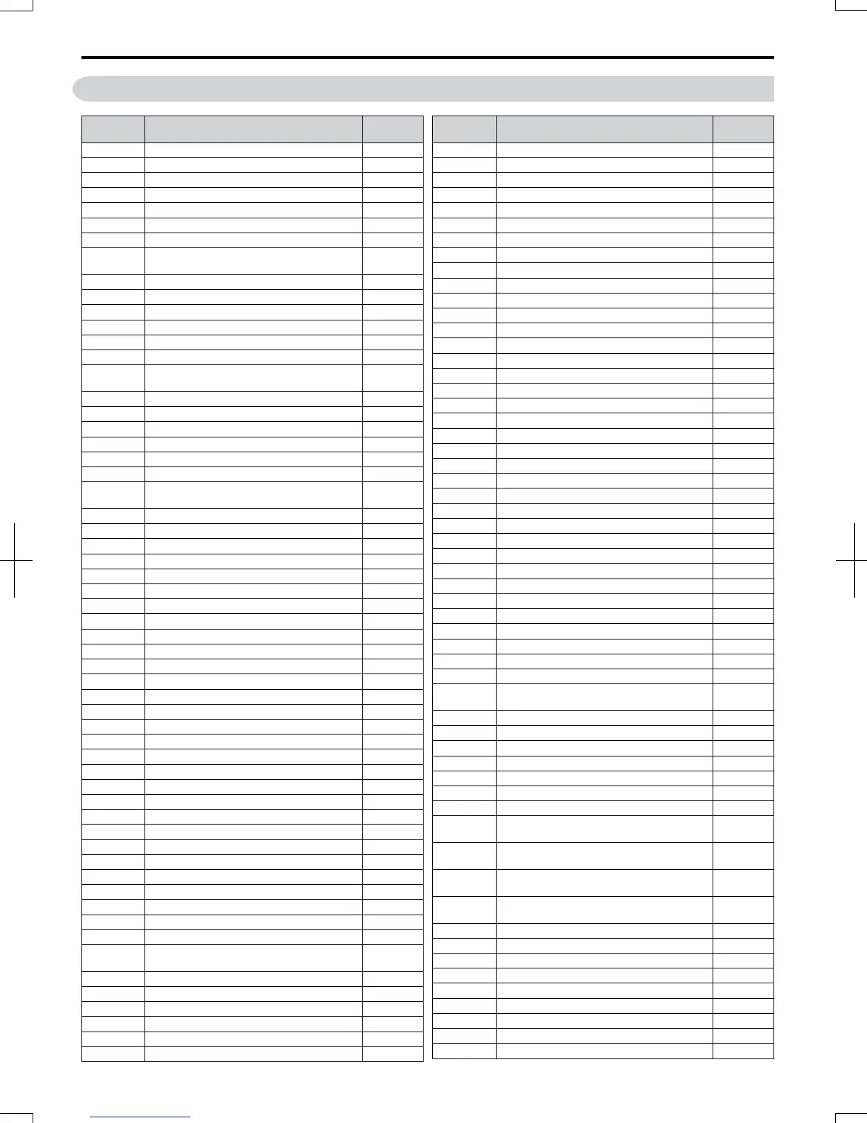
D.5 User Setting Table
No. Name
User
Setting
A1-01 Access Level Selection
A1-02 Control Method Selection
A1-03 Initialize Parameters
A1-04 Password 1
A1-05 Password 2
A1-06 Application Preset
A1-07 FBDs Function Selection
A2-02 to
A2-32
User Parameters, 1 to 32
A2-33 User Parameter Automatic Selection
b1-01 Frequency Reference Selection 1
b1-02 Run Command Selection 1
b1-03 Stopping Method Selection
b1-04 Reverse Operation Selection
b1-07 Local/Remote Run Selection
b1-08
Run Command Selection while in
Programming Mode
b1-14 Phase Order Selection
b1-15 Frequency Reference 2
b1-16 Run Command Source 2
b1-17 Run Command at Power Up
b2-01 DC Injection Braking Start Frequency
b2-02 DC Injection Braking Current
b2-03
DC Injection Braking Time/DC Excitation
Time at Start
b2-04 DC Injection Braking Time at Stop
b2-08 Magnetic Flux Compensation Value
b2-12 Short Circuit Brake Time at Start
b2-13 Short Circuit Brake Time at Stop
b3-01 Speed Search Selection
b3-02 Speed Search Deactivation Current
b3-03 Speed Search Deceleration Time
b3-05 Speed Search Delay Time
b3-06 Output Current 1 during Speed Search
b3-10 Speed Search Detection Compensation Gain
b3-14 Bi-Directional Speed Search Selection
b3-17 Speed Search Restart Current Level
b3-18 Speed Search Restart Detection Time
b3-19 Number of Speed Search Restarts
b3-24 Speed Search Method Selection
b3-25 Speed Search Retry Interval Time
b4-01 Timer Function On-Delay Time
b4-02 Timer Function Off-Delay Time
b5-01 PID Function Setting
b5-02 Proportional Gain Setting (P)
b5-03 Integral Time Setting (I)
b5-04 Integral Limit Setting
b5-05 Derivative Time
b5-06 PID Output Limit
b5-07 PID Offset Adjustment
b5-08 PID Primary Delay Time Constant
b5-09 PID Output Level Selection
b5-10 PID Output Gain Setting
b5-11 PID Output Reverse Selection
b5-12
PID Feedback Reference Missing Detection
Selection
b5-13 PID Feedback Loss Detection Level
b5-14 PID Feedback Loss Detection Time
b5-15 PID Sleep Function Start Level
b5-16 PID Sleep Delay Time
b5-17 PID Accel/Decel Time
b5-18 PID Setpoint Selection
No. Name
User
Setting
b5-19 PID Setpoint Value
b5-20 PID Setpoint Scaling
b5-34 PID Output Lower Limit
b5-35 PID Input Limit
b5-36 PID Feedback High Detection Level
b5-37 PID Feedback High Level Detection Time
b5-38 PID Setpoint / User Display
b5-39 PID Setpoint and Display Digits
b6-01 Dwell Reference at Start
b6-02 Dwell Time at Start
b6-03 Dwell Frequency at Stop
b6-04 Dwell Time at Stop
b8-01 Energy Saving Control Selection
b8-02 Energy Saving Gain
b8-03 Energy Saving Control Filter Time Constant
b8-04 Energy Saving Coefficient Value
b8-05 Power Detection Filter Time
b8-06 Search Operation Voltage Limit
C1-01 Acceleration Time 1
C1-02 Deceleration Time 1
C1-03 Acceleration Time 2
C1-04 Deceleration Time 2
C1-05 Acceleration Time 3 (Motor 2 Accel Time 1)
C1-06 Deceleration Time 3 (Motor 2 Decel Time 1)
C1-07 Acceleration Time 4 (Motor 2 Accel Time 2)
C1-08 Deceleration Time 4 (Motor 2 Decel Time 2)
C1-09 Fast-Stop Time
C1-10 Accel/Decel Time Setting Units
C1-11 Accel/Decel Time Switching Frequency
C2-01 S-Curve Characteristic at Accel Start
C2-02 S-Curve Characteristic at Accel End
C2-03 S-Curve Characteristic at Decel Start
C2-04 S-Curve Characteristic at Decel End
C3-01 Slip Compensation Gain
C3-02 Slip Compensation Primary Delay Time
C3-03 Slip Compensation Limit
C3-04
Slip Compensation Selection during
Regeneration
C3-05 Output Voltage Limit Operation Selection
C4-01 Torque Compensation Gain
C4-02 Torque Compensation Primary Delay Time
C4-03 Torque Compensation at Forward Start
C4-04 Torque Compensation at Reverse Start
C4-05 Torque Compensation Time Constant
C4-06 Torque Compensation Primary Delay Time 2
C5-01
ASR Proportional Gain 1 (for Simple PG V/f
Control)
C5-02
ASR Integral Time 1 (for Simple PG V/f
Control)
C5-03
ASR Proportional Gain 2 (for Simple PG V/f
Control)
C5-04
ASR Integral Time 2 (for Simple PG V/f
Control)
C5-05 ASR Limit (for Simple PG V/f Control)
C6-01 Duty Mode Selection
C6-02 Carrier Frequency Selection
C6-03 Carrier Frequency Upper Limit
C6-04 Carrier Frequency Lower Limit
C6-05 Carrier Frequency Proportional Gain
d1-01 Frequency Reference 1
d1-02 Frequency Reference 2
d1-03 Frequency Reference 3
D.5 User Setting Table
392
SIEP C710606 20 OYMC AC Drive - V1000 User Manual
7/16/2008-13:23

 Loading...


