No. Name
User
Setting
d1-04 Frequency Reference 4
d1-05 Frequency Reference 5
d1-06 Frequency Reference 6
d1-07 Frequency Reference 7
d1-08 Frequency Reference 8
d1-09 Frequency Reference 9
d1-10 Frequency Reference 10
d1-11 Frequency Reference 11
d1-12 Frequency Reference 12
d1-13 Frequency Reference 13
d1-14 Frequency Reference 14
d1-15 Frequency Reference 15
d1-16 Frequency Reference 16
d1-17 Jog Frequency Reference
d2-01 Frequency Reference Upper Limit
d2-02 Frequency Reference Lower Limit
d2-03 Master Speed Reference Lower Limit
d3-01 Jump Frequency 1
d3-02 Jump Frequency 2
d3-03 Jump Frequency 3
d3-04 Jump Frequency Width
d4-01 Frequency Reference Hold Function Selection
d4-03 Frequency Reference Bias Step (Up/Down 2)
d4-04
Frequency Reference Accel/Decel (Up/Down
2)
d4-05
Frequency Reference Bias Operation Mode
Selection (Up/Down 2)
d4-06 Frequency Reference Bias (Up/Down 2)
d4-07
Analog Frequency Reference Fluctuation
Limit (Up/Down 2)
d4-08
Frequency Reference Bias Upper Limit (Up/
Down 2)
d4-09
Frequency Reference Bias Lower Limit (Up/
Down 2)
d4-10
Up/Down Frequency Reference Limit
Selection
d4–11 Bi-directional Output Selection
d4–12 Stop Position Gain
d7-01 Offset Frequency 1
d7-02 Offset Frequency 2
d7-03 Offset Frequency 3
E1-01 Input Voltage Setting
E1-03 V/f Pattern Selection
E1-04 Max Output Frequency
E1-05 Max Voltage
E1-06 Base Frequency
E1-07 Mid Output Frequency
E1-08 Mid Output Frequency Voltage
E1-09 Minimum Output Freq.
E1-10 Minimum Output Freq. Voltage
E1-11 Mid Output Frequency 2
E1-12 Mid Output Frequency Voltage 2
E1-13 Base Voltage
E2-01 Motor Rated Current
E2-02 Motor Rated Slip
E2-03 Motor No-Load Current
E2-04 Number of Motor Poles
E2-05 Motor Line-to-Line Resistance
E2-06 Motor Leakage Inductance
E2-07 Motor Iron-Core Saturation Coefficient 1
E2-08 Motor Iron-Core Saturation Coefficient 2
E2-09 Motor Mechanical Loss
E2-10 Motor Iron Loss for Torque Compensation
E2-11 Motor Rated Output
E2-12 Motor Iron-Core Saturation Coefficient 3
No. Name
User
Setting
E3-01 Motor 2 Control Method Selection
E3-04 Motor 2 Max Output Frequency
E3-05 Motor 2 Max Voltage
E3-06 Motor 2 Base Frequency
E3-07 Motor 2 Mid Output Frequency
E3-08 Motor 2 Mid Output Frequency Voltage
E3-09 Motor 2 Minimum Output Freq
E3-10 Motor 2 Minimum Output Freq. Voltage
E3-11 Motor 2 Mid Output Freq. 2
E3-12 Motor 2 Mid Output Freq. Voltage 2
E3-13 Motor 2 Base Voltage
E4-01 Motor 2 Rated Current
E4-02 Motor 2 Rated Slip
E4-03 Motor 2 Rated No-Load Current
E4-04 Motor 2 Motor Poles
E4-05 Motor 2 Line-to-Line Resistance
E4-06 Motor 2 Leakage Inductance
E4-07
Motor 2 Motor Iron-Core Saturation
Coefficient 1
E4-08
Motor 2 Motor Iron-Core Saturation
Coefficient 2
E4-09 Motor 2 Mechanical Loss
E4-10 Motor 2 Iron Loss
E4-11 Motor 2 Rated Capacity
E4-12 Motor 2 Iron-Core Saturation Coefficient 3
E4-14 Motor 2 Slip Compensation Gain
E4-15 Torque Compensation Gain - Motor 2
E5-01 Motor Code Selection (PM motor)
E5-02 Motor Rated Capacity (PM motor)
E5-03 Motor Rated Current (PM motor)
E5-04 Motor Poles (PM motor)
E5-05 Motor Armature Resistance (PM motor)
E5-06 Motor d Axis Inductance (PM motor)
E5-07 Motor q Axis Inductance (PM motor)
E5-09
Motor Induction Voltage Constant 1 (PM
motor)
E5–24
Motor Induction Voltage Constant 2 (PM
motor)
E5-24
Motor Induction Voltage Parameter 2 (PM
motor)
F1-02
Operation Selection at PG Open Circuit
(PGO)
F1-03
Operation Selection at Overspeed (OS) (for
Simple PG V/f)
F1-04
Operation Selection at Deviation (for Simple
PG V/f Control)
F1-08
Overspeed Detection Level (for Simple PG V/
f Control)
F1-09
Overspeed Detection Delay Time (for Simple
PG V/f Control)
F1-10
Excessive Speed Deviation Detection Level
(for Simple PG V/f Control)
F1-11
Excessive Speed Deviation Detection Delay
Time (for Simple PG V/f Control)
F1-14
PG Open-Circuit Detection Time (for Simple
PG V/f Control)
F6-01 Communications Error Operation Selection
F6-02 External Fault from Comm. Option Selection
F6-03
External Fault from Comm. Option Operation
Selection
F6-04 Trace Sampling Rate
F6-10 CC-Link Node Address
F6-11 CC-Link Communications Speed
F6-14 BUS Error Auto Reset
F6-30 PROFIBUS-DP Node Address
F6-31 PROFIBUS-DP Clear Mode Selection
F6-32 PROFIBUS-DP Map Selections
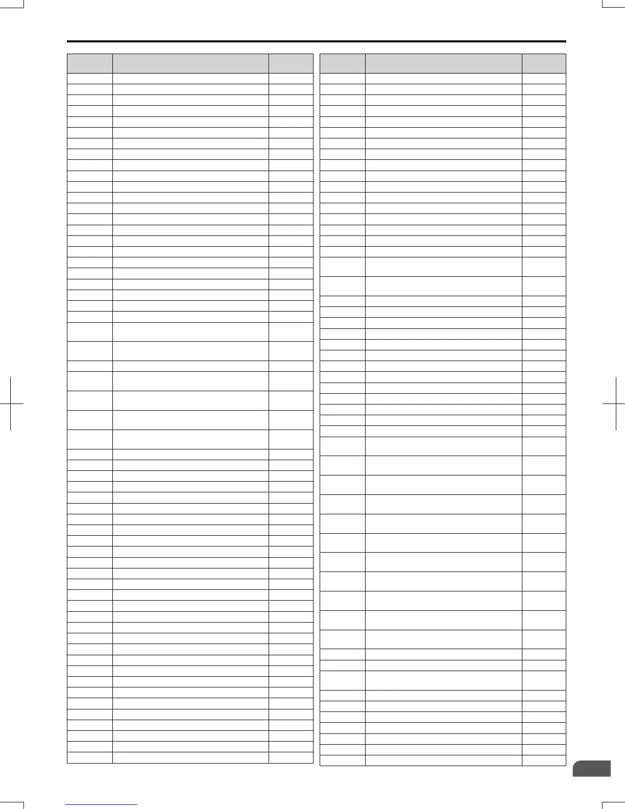
D.5 User Setting Table
SIEP C710606 20 OYMC AC Drive - V1000 User Manual
393
D
Standards Compliance
7/16/2008-13:23