u
Terminal Configuration
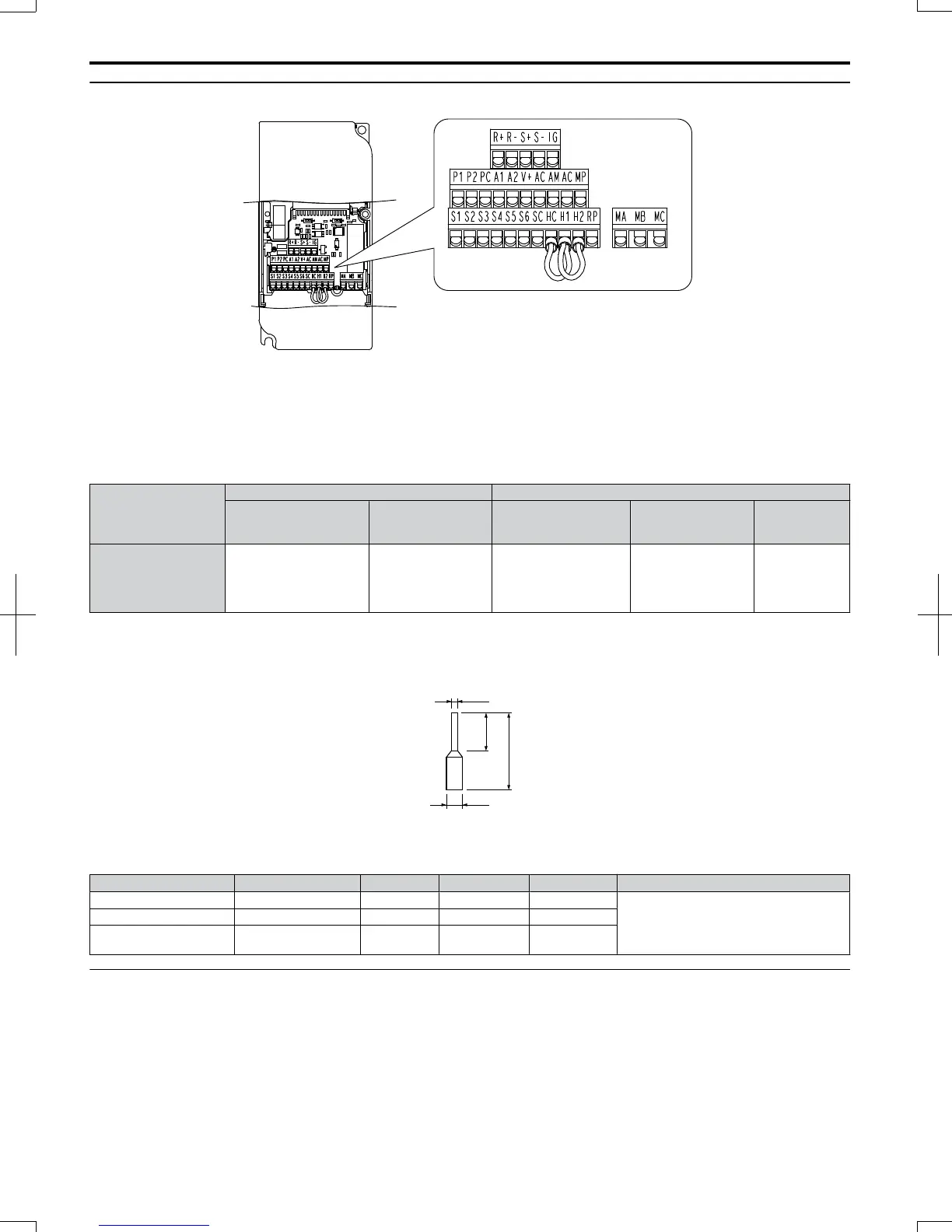
Figure 3.16 Removable Control Circuit Terminal Block
n
Wire Size
Select the appropriate wires and crimp terminals from Table 3.9. Crimp a ferrule to signal wiring to improve wiring
simplicity and reliability.
Table 3.9 Wire Size Specifications (Same for All Models)
Terminal
Bare Wire Terminal Ferrule-Type Terminal
Applicable wire size
mm
2
(AWG)
Recomm. mm
2
(AWG)
Applicable wire size
mm
2
(AWG)
Recomm. mm
2
(AWG)
Wire Type
S1-S6, SC, RP, +V, A1,
A2, AC, HC, H1, H2, P1,
P2, PC, MP, AM, AC, S
+, S-, R+, R-, IG, MA,
MB, MC
Stranded wire:
0.2 to 1.0
(24 to 16)
Solid wire: 0.2 to 1.5
(24 to 16)
0.75 (18)
0.25 to 0.5
(24 to 20)
0.5 (20) Shielded line, etc.
n
Ferrule-Type Wire Terminations
Crimp a ferrule to signal wiring to improve wiring simplicity and reliability. Use CRIMPFOX ZA-3, a crimping tool
manufactured by PHOENIX CONTACT.
d1
d2
8 mm
L
Figure 3.17
Ferrule Dimensions
Table 3.10 Ferrule Terminal Types and Sizes
Size mm
2
(AWG)
Type L (mm) d1 (mm) d2 (mm) Manufacturer
0.25 (24) AI 0.25-8YE 12.5 0.8 1.8
PHOENIX CONTACT
0.34 (22) AI 0.34-8TQ 10.5 0.8 1.8
0.5 (20)
AI 0.5-8WH or
AI 0.5–8OG
14 1.1 2.5
u
Wiring Procedure
This section describes the proper procedures and preparations for wiring the control terminals.
WARNING! Electrical Shock Hazard. Do not remove covers or touch the circuit boards while the power is on. Failure to comply could
result in death or serious injury.
NOTICE: Separate control circuit wiring from main circuit wiring (terminals R/L1, S/L2, T/L3, B1, B2, U/T1, V/T2, W/T3, -, +1, +2) and
other high-power lines. Improper wiring practices could result in drive malfunction due to electrical interference.
NOTICE: Separate wiring for digital output terminals MA, MB and MC from wiring to other control circuit lines. Improper wiring practices
could result in drive or equipment malfunction or nuisance trips.
NOTICE: Use a class 2 power supply (UL standard) when connecting to the control terminals. Improper application of peripheral devices
could result in drive performance degradation due to improper power supply.
3.7
Control Circuit Wiring
52
SIEP C710606 20 OYMC AC Drive - V1000 User Manual
7/16/2008-13:23