3.7 Control Circuit Wiring
NOTICE: Do not solder the ends of wire connections to the drive. Soldered wire connections can loosen over time. Improper wiring
practices could result in drive malfunction due to loose terminal connections.
+
-
Forward run/stop
Reverse run/stop
External fault
Fault reset
Multi-step
speed 2
DIP
switch S3
Digital inputs
(default setting)
V1000
Control circuit
S1
S2
S3
S4
S5
S6
24 V
+
24 V 8 mA
SC
Multi-step
speed 1
main/aux switch
Sink
Source
<1>
<2>
V I
Digital output
5 ~ 48 Vdc
2 to 50 mA
(default setting)
Digital output
250 Vac, 10 mA to 1 A
30 Vdc, 10 mA to 1 A
(default setting)
DIP switch S1
Option card
connector
MA
MB
MC
Fault
0 V
P1
P2
MP
AM
AC
PC
R
+V
A1
A2
AC
Pulse train input
(max. 32 kHz)
Setting power supply
+10.5 max. 20 mA
During Run
(photocoupler 1)
Frequency agree
(photocoupler 2)
Photocoupler
output common
0 to +10 Vdc
(2 mA)
Shield ground
terminal
AM
P
0 to +10 V (20 k )
0 to +10 V (20 k )
(0)4 to 20 mA (250 )
Pulse train output
0 to 32 kHz
Analog monitor
output
Comm.
connector
IG
R
+
R
-
S
+
S
-
MEMOBUS/
Modbus comm.
RS-485/422
Termination
resistor
, 1/2 W
Monitor
output
DIP
switch
S2
Cable shield ground
120 , 1/2 W
main circuit terminal
shielded line
twisted-pair shielded line
control terminal
Safe Disable
Input
Safety switch
H2
Jumper
HC
H1
2 k
Main speed
frequency
reference.
Multi-function
programmable
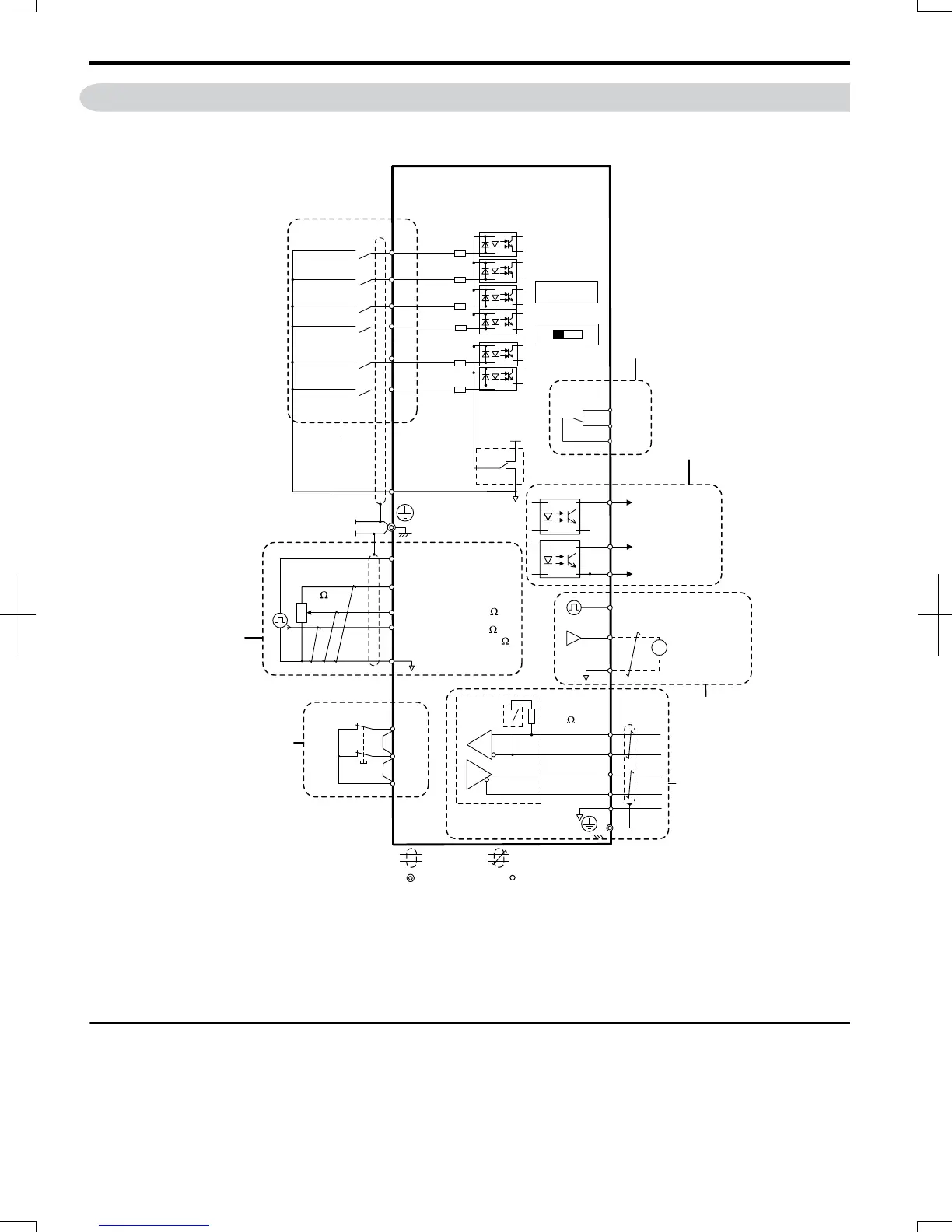
Figure 3.14 Control Circuit Connection Diagram
<1> Connected using sequence input signal (S1 to S6) from NPN transistor; Default: sink mode (0 V com)
<2> Use only the +24 V internal power supply in sinking mode; the source mode requires an external power supply. Refer
to I/O Connections on page 55.
u
Control Circuit Terminal Block Functions
Drive parameters determine which functions apply to the multi-function digital inputs (S1 to S6), multi-function digital
outputs (MA, MB), multi-function pulse inputs and outputs (RP, MP) and multi-function photocoupler outputs (P1, P2).
The default is called out next to each terminal in Figure 3.14.
WARNING! Sudden Movement Hazard. Always check the operation and wiring of control circuits after being wired. Operating a drive
with untested control circuits could result in death or serious injury.
3.7
Control Circuit Wiring
50
SIEP C710606 20 OYMC AC Drive - V1000 User Manual
7/16/2008-13:23