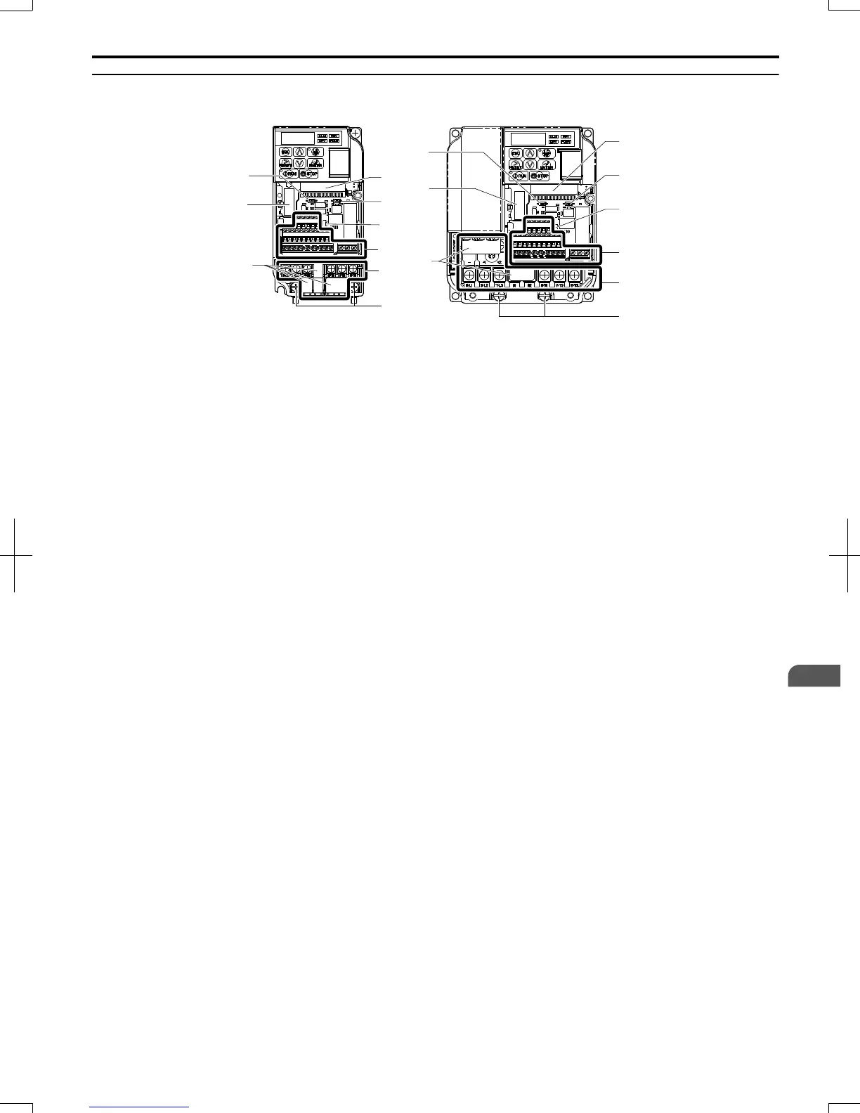
EasyManuals Logo

Omron V1000 User Manual

Omron V1000
411 pages
To Next Page IconTo Next Page
To Previous Page IconTo Previous Page
Page #26 background imageLoading...
Page #26 background image
u
Front Views
I
H
F
A
B
C
D
E
G
I
A
B
C
D
E
F
G
H
VZAB0P1B
VZA42P2B
A Terminal board connector
B DIP switch S1 Refer to DIP Switch S1 Analog
Input Signal Selection on page 57
C DIP switch S3 Refer to Sinking/Sourcing Mode
Switch on page 55
D Control circuit terminal Refer to Control Circuit
Wiring on page 50
E Main circuit terminal Refer to Wiring the Main
Circuit Terminal on page 49
F Ground terminal
G Terminal cover
H Option card connector Refer to Connecting the
Option Card on page 284
I DIP switch S2 Refer to MEMOBUS/Modbus
Termination on page 58
Figure 1.5 Front Views of Drives
1.4 Component Names
SIEP C710606 20 OYMC AC Drive - V1000 User Manual
25
1
Receiving
7/16/2008-13:22

Table of Contents

Other manuals for Omron V1000

Questions and Answers:

Question and Answer IconNeed help?

Do you have a question about the Omron V1000 and is the answer not in the manual?

Omron V1000 Specifications

General IconGeneral
Cooling MethodFan cooling
Enclosure RatingIP20
CommunicationModbus RTU
Output Power0.4-15kW
Output Frequency Range0 to 400 Hz
Overload Capacity150% for 60 seconds
Protection FeaturesOvercurrent, Overvoltage, Undervoltage, Overheating, Short Circuit
Operating Temperature-10°C to +50°C
Storage Temperature-20°C to +65°C
Humidity5 to 95% RH (non-condensing)
Supply Voltage200-240V AC (3-phase)

Related product manuals