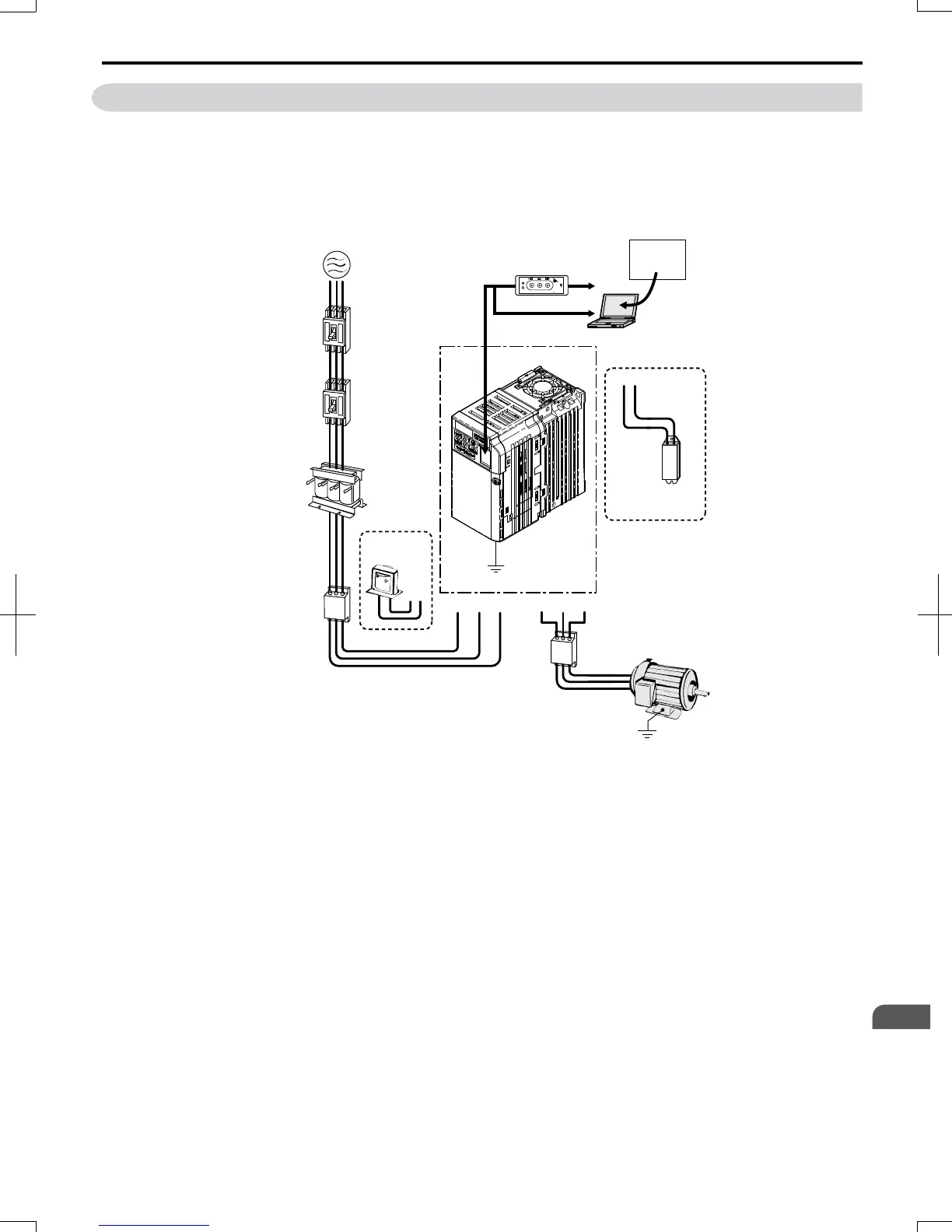
8.3 Connecting Peripheral Devices
Figure 8.1 illustrates how the drive and motor connect together with various peripheral devices.
• Refer to peripheral device option manual for detailed installation instructions.
Drive
Ground
PC
Ground
Motor
Engineering software tools
U/T1 V/T2 W/T3R/L1 S/L2
+2+1
T/L3
CX - Drive
B1 B2
AC reactor
Input side
noise filter
DC reactor
Braking
resistor
unit
Output side
noise filter
To serial comm port
USB Copy Unit
(RJ-45/USB adapter)
Copy
V
erify
Read
LOCK
YASKAWA
JVOP-181
USB Copy Unit
COM ERR
Power
Supply
Line
breaker
(MCCB)
Leakage
breaker
Figure 8.1 Connecting Peripheral Devices
8.3 Connecting Peripheral Devices
SIEP C710606 20 OYMC AC Drive - V1000 User Manual
277
8
Peripheral Devices &
Options
7/16/2008-13:23