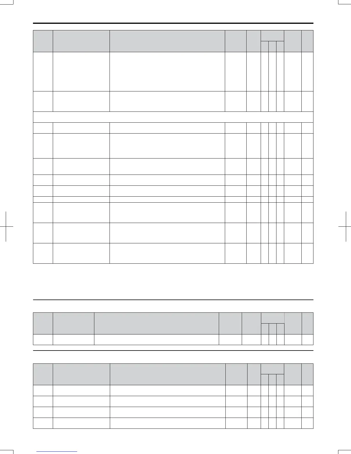
No. Name Description Range Def.
Control
Mode
Addr.
Hex
Pg.
V/f
O
LV
P
M
o3-01 Copy Function Selection
Selects the copy function operation.
0: No action
1: READ
2: COPY
3: VERIFY
NOTE: When using the copy function, the drive model
number (o2-04) and the software number (U1-14) must
match or an error will occur.
0 to 3 0 A A A 515 —
o3-02
Copy Function READ
Permission
Locks the READ operation to prevent accidental overwriting
of the data stored in the LED operator.
0: READ operation prohibited
1: READ operation allowed
0, 1 0 A A A 516 —
o4: Maintenance Period
Use o4 parameters to perform maintenance.
o4-01
Accumulated Operation
Time Setting
Sets the value for the cumulative operation time of the drive
in units of 10 h.
0 to 9999 0 A A A 50B 216
o4-02
Accumulated Operation
Time Selection
Determines, how the cumulative operation time (U4-01) is
counted.
0: Logs power-on time
1: Logs operation time when the drive output is active (output
operation time).
0 to 1 0 A A A 50C 216
o4-03
Cooling Fan Operation Time
Setting
Sets the value of the fan operation time monitor U4-03 in
units of 10 h.
<61>
0 to 9999 0 A A A 50E 216
o4-05
Capacitor Maintenance
Setting
Sets the value of the capacitor maintenance time monitor
U4-05.
0 to 150 0% A A A 51D 217
o4-07
Soft Charge Bypass Relay
Maintenance Setting
Sets the value of the Soft Charge Bypass Relay Maintenance
monitor U4-06.
0 to 150 0% A A A 523 217
o4-09 IGBT Maintenance Setting Sets the value of the IGBT Maintenance monitor U4-07. 0 to 150 0% A A A 525 217
o4-11 U2, U3 Initialize Selection
Selects if U2- (Fault Trace), U3- (Fault History)
monitors are reset at drive initialization.
0: Saves the fault monitor data
1: Resets the fault monitor data
0 to 1 0 A A A 510 217
o4-12
kWh Monitor Initialize
Selection
Selects if U4-10 and U4-11 (kWh monitor) are reset at drive
initialization.
0: Saves the U4-10 and U4-11 monitor data.
1: Resets the U4-10 and U4-11 monitor data.
0 to 1 0 A A A 512 217
o4-13
Number of Run Commands
Initialize Selection
Selects if the Run command counter (U4-02) is reset at drive
initialization.
0: Saves the number of Run commands
1: Resets the number of Run commands
0 to 1 0 A A A 528 217
<9> Default setting value is dependent on parameter E1-01, Input Voltage Setting.
<11> Default setting value is dependent on parameter o1-03, Digital Operator Display Selection.
<12> Default setting value is dependent on parameter o2-04, Drive Model Selection.
<22> Parameter can be changed during run.
<61> Valid for drive software 1011 and later. Value is set in 1 h units for older software.
u
q: FBDs Parameters
No. Name Description Range Def.
Control
Mode
Addr.
Hex
Pg.
V/f
O
LV
P
M
q1-01 to
q6-07
FBDs Parameters Reserved for FBDs. - - A A Α - —
u
r: FBDs Connection Parameters
No. Name Description Range Def.
Control
Mode
Addr.
Hex
Pg.
V/f
O
LV
P
M
r1-01
FBDs Connection Parameter
1 (upper)
Parameter 1 for connecting FBDs (upper).
0 to
FFFFH
0 – A A 1840 —
r1-02
FBDs Connection Parameter
1 (lower)
Parameter 1 for connecting FBDs (lower).
0 to
FFFFH
0 – A A 1841 —
r1-03
FBDs Connection Parameter
2 (upper)
Parameter 2 for connecting FBDs (upper).
0 to
FFFFH
0 – A A 1842 —
r1-04
FBDs Connection Parameter
2 (lower)
Parameter 1 for connecting FBDs (lower).
0 to
FFFFH
0 – A A 1843 —
B.2 Parameter Table
330
SIEP C710606 20 OYMC AC Drive - V1000 User Manual
7/16/2008-13:23