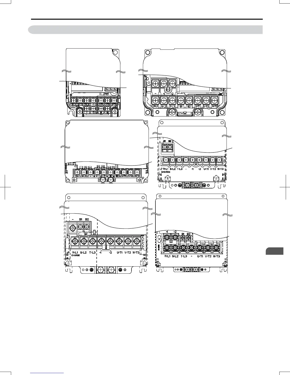
3.4 Terminal Block Configuration
The figures in this section provide illustrations of the main circuit terminal block configurations of the different drive sizes.
VZAB0P1, B0P2, B0P4
VZA20P1, 20P2, 20P4, 20P7
VZA2011
VZA4011, 4015
VZA2015
VZA25P5, 27P5
VZA45P5, 47P5
VZAB0P7, B1P5, B2P2
VZA21P5, 22P2, 24P0
VZA40P2, 40P4, 40P7, 41P5
42P2, 43P0, 44P0
Models:
Model: VZAB4P0
Models:
Model:
Models:
Models:
Figure 3.5 Main Circuit Terminal Block Configurations
3.4
Terminal Block Configuration
SIEP C710606 20 OYMC AC Drive - V1000 User Manual
43
3
Electrical Installation
7/16/2008-13:23