B
A
C
F
G
D
E
R/L1
MCCB
S/L2
T/L3
U/T1
V/T2
W/T3
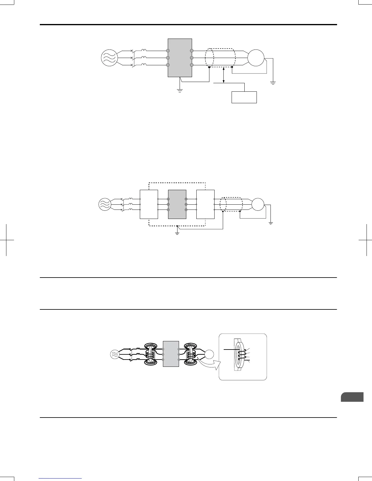
A – Power supply
B – Drive
C – Shielded motor cable
D – Motor
E – Separate at least 30 cm
F – Controller
G – Signal line
Figure 8.8 Preventing Induced Noise
Reducing Radiated/Radio Frequency Noise
The drive, input lines, and output lines generate radio frequency noise. Use noise filters on input and output sides and
install the drive in a metal enclosure panel to reduce radio frequency noise.
Note: The cable running between the drive and motor should be as short as possible.
C ED
B
F
A
R/L1
MCCB
S/L2
T/L3
U/T1
V/T2
W/T3
G
A – Metal enclosure
B – Power supply
C – Noise filter
D – Drive
E – Noise filter
F – Shielded motor cable
G – Motor
Figure 8.9 Reducing Radio Frequency Noise
u
EMC Filter Installation
This drive is tested according to European standards EN61800-3 and it complies with the EMC guidelines. Refer to EMC
Filter Installation on page 383 for details about EMC filter selection and installation.
u
Zero-Phase Reactor
A zero-phase reactor can be used to reduce the noise on the input and output sides of the drive.
Close-up of V/T2-phase wiring
1st pass
4th pass
3rd pass
2nd pass
D
E
F
C
B
A
Pass each wire (U/T1, V/T2, W/T3)
through the core 4 times.
R/L1
S/L2
T/L3
U/T1
V/T2
W/T3
A –
Power supply
B – MCCB
C – Zero-phase reactor on input side
D – Drive
E – Zero-phase reactor on output side
F – Motor
Figure 8.10 Zero-Phase Reactor
u
Installing a Motor Thermal Overload (oL) Relay on the Drive Output
Motor thermal overload relays protect the motor by disconnecting power lines to the motor due to a motor overload
condition.
Install a motor thermal overload relay between the drive and motor:
8.4
Installing Peripheral Devices
SIEP C710606 20 OYMC AC Drive - V1000 User Manual
281
8
Peripheral Devices &
Options
7/16/2008-13:23