NOTICE: Insulate shields with tape or shrink tubing to prevent contact with other signal lines and equipment. Improper wiring practices
could result in drive or equipment malfunction due to short circuit.
NOTICE: Connect the shield of shielded cable to the appropriate ground terminal. Improper equipment grounding could result in drive
or equipment malfunction or nuisance trips.
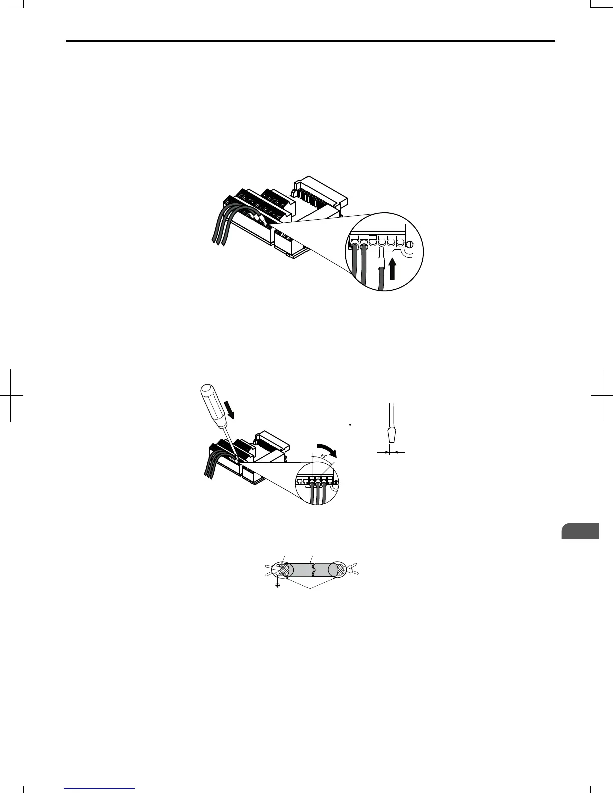
Prepare the wire ends to connect them to the terminal board as shown in Figure 3.18. Use ferrules or solid wires; the
stripping length for solid wires is 8 mm.
NOTICE: Do not tighten screws beyond the specified tightening torque. Failure to comply may damage the terminal block.
NOTICE: Use shielded twisted-pair cables as indicated to prevent operating faults. Improper wiring practices could result in drive or
equipment malfunction due to electrical interference.
Connect control wires as shown in the following figure:
Terminal Board
Control Wires
Push wire end
into terminal
Figure 3.18 Connecting Wires to the Control Terminals
To disconnect control wires from the terminals use the procedure described in the following figure. Grasp the wire where
it enters the terminal with a pair of pliers, then use a slotted–tip screwdriver to release the terminal and pull the wire out.
If it fits tightly, i.e., if ferrules are used, turn the wire 45 degrees and gently remove it. Use this procedure to remove the
wire jumper between terminals HC, H1, and H2 that is installed at shipping.
Terminal Board
Control Wires
Push down to open
the terminal
Turn the wire ~ 45
and pull it out of the
terminal.
Use a screwdriver with a blade
width of max 2.5 mm and a
thickness of max 0.4 mm
Figure 3.19 Removing Wires from the Terminal Board
A
F
C
D
E
B
A – Drive side
B – Connect shield to ground terminal of drive.
C – Insulation
D – Control device side
E – Shield sheath (Insulate with tape)
F – Shield
Figure 3.20 Preparing the Ends of Shielded Cables
When setting the frequency by analog reference from an external potentiometer, use shielded twisted-pair wires and ground
the shield of twisted-pair wires to the ground terminal of the drive.
NOTICE: The analog signal lines between the drive and the operator station or peripheral equipment should not exceed 50 meters
when using an analog signal from a remote source to supply the frequency reference. Failure to comply could result in poor system
performance.
3.7
Control Circuit Wiring
SIEP C710606 20 OYMC AC Drive - V1000 User Manual
53
3
Electrical Installation
7/16/2008-13:23