RP
+V
A1
A2
AC
A
B
C
D
E
F
G
2 k
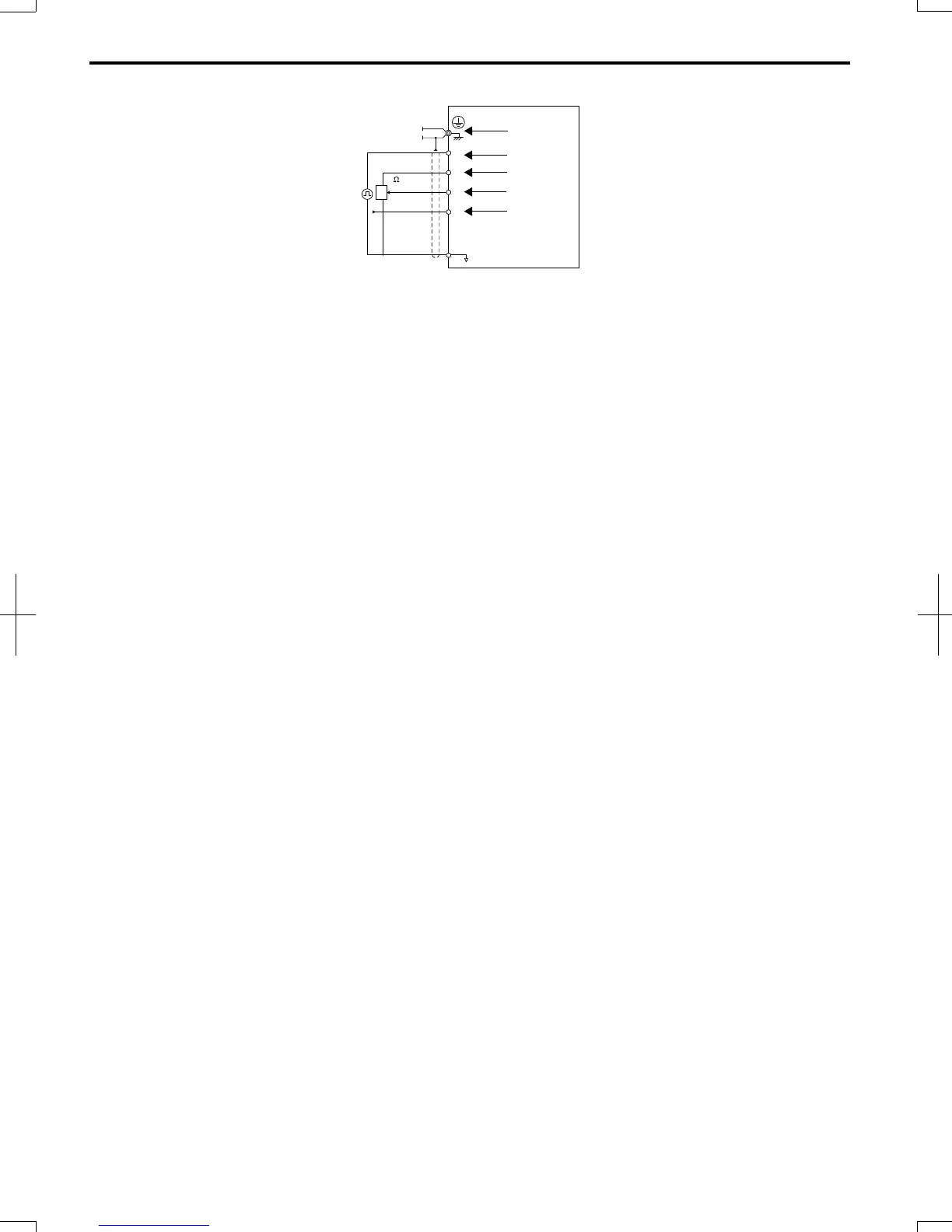
A – Drive
B – Ground terminal (shield connection)
C – (RP) Pulse train (maximum 32 kHz)
D – (+V) Frequency setting power source +10.5 Vdc
maximum 20 mA
E – (A1) Main speed frequency reference 0 to +10
Vdc (20 kΩ)
F – (A2) Multi-function analog input
0 to +10 Vdc (20 kΩ) or
4 to 20 mA (250 Ω)/
0 to 20 mA (250 Ω)
G – Frequency setting potentiometer
Figure 3.21
Wiring the Frequency Reference to the Control Circuit Terminals (External Reference)
3.7 Control Circuit Wiring
54
SIEP C710606 20 OYMC AC Drive - V1000 User Manual
7/16/2008-13:23