No. Name
User
Setting
F6-35 CANopen Node ID Selection
F6-36 CANopen Communication Speed
F6-40 CompoNet Node ID
F6-41 CompoNet Speed
F6-50 DeviceNet MAC Address
F6-51 DeviceNet Communication Speed
F6-52 DeviceNet PCA Setting
F6-53 DeviceNet PPA Setting
F6-54 DeviceNet Idle Mode Fault Detection
F6-56 DeviceNet Speed Scaling
F6-57 DeviceNet Current Scaling
F6-58 DeviceNet Torque Scaling
F6-59 DeviceNet Power Scaling
F6-60 DeviceNet Voltage Scaling
F6-61 DeviceNet Time Scaling
F6-62 DeviceNet Heartbeat Interval
F7-01 Ethernet IP Address 1
F7-02 Ethernet IP Address 2
F7-03 Ethernet IP Address 3
F7-04 Ethernet IP Address 4
F7-05 Subnet Mask 1
F7-06 Subnet Mask 2
F7-07 Subnet Mask 3
F7-08 Subnet Mask 4
F7-09 Gateway Address 1
F7-10 Gateway Address 2
F7-11 Gateway Address 3
F7-12 Gateway Address 4
F7-13 Dress Mode at Startup
F7-14 Security Password
F7-15 Duplex Mode Selection
F7-18 Communication Speed Selection
F7-19 Web Page Access
F7-20 Gateway Selection
F7-21 Communication Loss Time Out
H1-01
Multi-Function Digital Input Terminal S1
Function Selection
H1-02
Multi-Function Digital Input Terminal S2
Function Selection
H1-03
Multi-Function Digital Input Terminal S3
Function Selection
H1-04
Multi-Function Digital Input Terminal S4
Function Selection
H1-05
Multi-Function Digital Input Terminal S5
Function Selection
H1-06
Multi-Function Digital Input Terminal S6
Function Selection
H2-01
Terminal MA, MB and MC Function
Selection (relay)
H2-02
Terminal P1 Function Selection (open-
collector)
H2-03
Terminal P2 Function Selection (open-
collector)
H2-06 Watt Hour Output Unit Selection
H3-01 Terminal A1 Signal Level Selection
H3-02 Terminal A1 Function Selection
H3-03 Terminal A1 Gain Setting
H3-04 Terminal A1 Bias Setting
H3-09 Terminal A2 Signal Level Selection
H3-10 Terminal A2 Function Selection
H3-11 Terminal A2 Gain Setting
H3-12
Frequency Reference (Current) Terminal A2
Input Bias
H3-13 Analog Input Filter Time Constant
H4-01
Multi-Function Analog Output (Terminal AM
Monitor Selection)
No. Name
User
Setting
H4-02
Multi-Function Analog Output (Terminal AM
Output Gain)
H4-03
Multi-Function Analog Output (Terminal AM
Output Bias)
H5-01 Drive Node Address
H5-02 Communication Speed Selection
H5-03 Communication Parity Selection
H5-04 Stopping Method After Communication Error
H5-05 Communication Fault Detection Selection
H5-06 Drive Transmit Wait Time
H5-07 RTS Control Selection
H5-09 CE Detection Time
H5-10
Unit Selection for MEMOBUS/Modbus
Register 0025H
H5-11 Communications ENTER Function Selection
H5-12 Run Command Method Selection
H6-01
(Terminal RP) Pulse Train Input Function
Selection
H6-02 Pulse Train Input Scaling
H6-03 Pulse Train Input Gain
H6-04 Pulse Train Input Bias
H6-05 Pulse Train Input Filter Time
H6-06 (Terminal MP) Pulse Train Monitor Selection
H6-07 Pulse Train Monitor Scaling
L1-01 Motor Overload Protection Selection
L1-02 Motor Overload Protection Time
L1-03
Motor Overheat Alarm Operation Selection
(PTC input)
L1-04
Motor Overheat Fault Operation Selection
(PTC input)
L1-05
Motor Temperature Input Filter Time (PTC
input)
L1-13
Continuous Electrothermal Operation
Selection
L2-01 Momentary Power Loss Operation Selection
L2-02 Momentary Power Loss Ride-Thru Time
L2-03
Momentary Power Loss Minimum Baseblock
Time
L2-04
Momentary Power Loss Voltage Recovery
Ramp Time
L2-05 Undervoltage Detection Level (Uv)
L2-06 KEB Deceleration Time
L2-07 Momentary Power Loss Ride-Thru Time
L2-08 Minimum Frequency Gain at KEB Start
L2-11 Desired DC Bus Voltage During KEB
L3-01
Stall Prevention Selection during
Acceleration
L3-02 Stall Prevention Level during Acceleration
L3-03 Stall Prevention Limit during Acceleration
L3-04
Stall Prevention Selection during
Deceleration
L3-05 Stall Prevention Selection during Run
L3-06 Stall Prevention Level during Run
L3-11 ov Suppression Function Selection
L3-17
Overvoltage Suppression and Deceleration
Stall (Desired DC Bus Voltage during Motor
Stall)
L3-20 Main Power Circuit Voltage Adjustment Gain
L3-21 Accel/Decel Rate Calculation Gain
L3-22
Deceleration Time at Stall Prevention during
Acceleration
L3-23
Automatic Reduction Selection for Stall
Prevention during Run
L3-24
Motor Acceleration Time for Inertia
Calculations
L3-25 Load Inertia Ratio
L4-01 Speed Agreement Detection Level
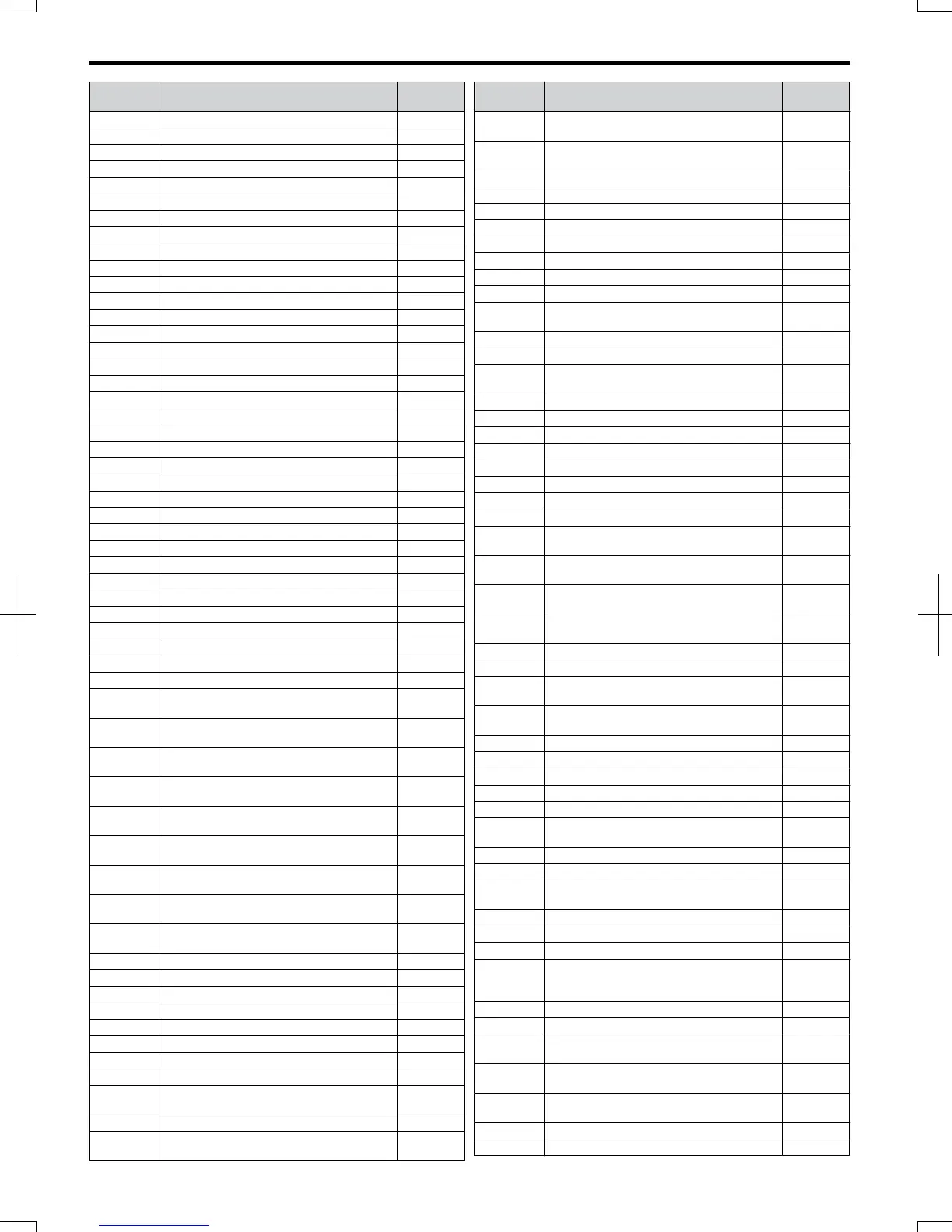
D.5 User Setting Table
394
SIEP C710606 20 OYMC AC Drive - V1000 User Manual
7/16/2008-13:23
 Loading...


