The frequency detection function is used for controlling the brake.
Although the drive output will be shut off, the drive will maintain the frequency reference if an external Baseblock
command is given (H1-xx = 8/9) and the Run command remains active. Disable the Frequency detection during Baseblock
by setting parameter L4-07 = “0” to prevent the brake remaining open during Baseblock condition.
Brake Control During Safe Disable Input
If the Safe Disable input is released, the drive output will shut off and the frequency reference will reset to 0 and the brake
will close, regardless if the Run command is active. The Run command must be cycled before the drive can restart.
The table below shows how to set up the drive when using output terminals P2-PC as brake control output.
Function Parameter Setting V/f OLV OLV for PM
Frequency Detection 2
Digital Output (Brake Control)
H2-03 5 O O O
Frequency Detection
during Baseblock
L4-07 0 O O O
Frequency Detection Level
(Brake Open Frequency)
L4-01
1.0 to 3.0 Hz
<1>
O O O
Frequency Detection Width
(Brake Close Bandwidth)
L4-02
0.0 to 0.5 Hz
<2>
O O O
<1> This is the setting recommended when using Open Loop Vector Control. In V/f Control, set the level as the motor rated slip frequency plus
0.5 Hz. Not enough motor torque will be created if this value is set too low, and the load may tend to slip. Make sure this value is greater than
the minimum output frequency and greater than the value of L4-02 as shown in the diagram below. If set too high, however, there may be a
jolt at start.
<2> Hysteresis for Frequency Detection 2 can be adjusted by changing the Frequency Detection Width (L4-02) between 0.0 and 0.5 Hz. If the load
slips during stop, make changes in steps of 0.1 Hz until the load no longer slips.
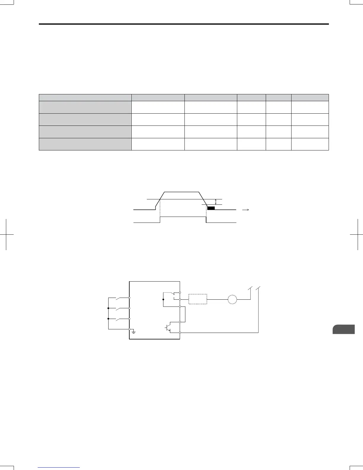
L4-02
L4-01
OFF
ON
time
output
frequency
Frequency
Dectection 2
Figure 4.10 Frequency Detection 2
The braking sequence should be designed as follows:
• A normally open signal (N.O.) should be used to control the brake so that it is released when terminal P2-PC closes.
• When a fault signal is output, the brake should close.
Note: The drawing below shows a control wiring example for the crane application preset:
Safety
Circuit
BR
Drive
( Forward(
24 V
Frequency Detect 2
UP
DOWN
High speed
Low speed
( Reverse(
S2
( Multi-step speed 2)
MA
MB
MC
P2
PC
S6
SC
Fault Contact
Holding brake
auxilary relay coil
S1
Figure 4.11 Brake Control Wiring
• When changing the speed using an analog signal, make sure that the source of the frequency reference is assigned to the
control circuit terminals (b1-01 = 1).
• A sequence to open and close the holding brake appears in the diagram below.
4.6
Application Selection
SIEP C710606 20 OYMC AC Drive - V1000 User Manual
85
4
Start-Up Programming
& Operation
7/16/2008-13:23