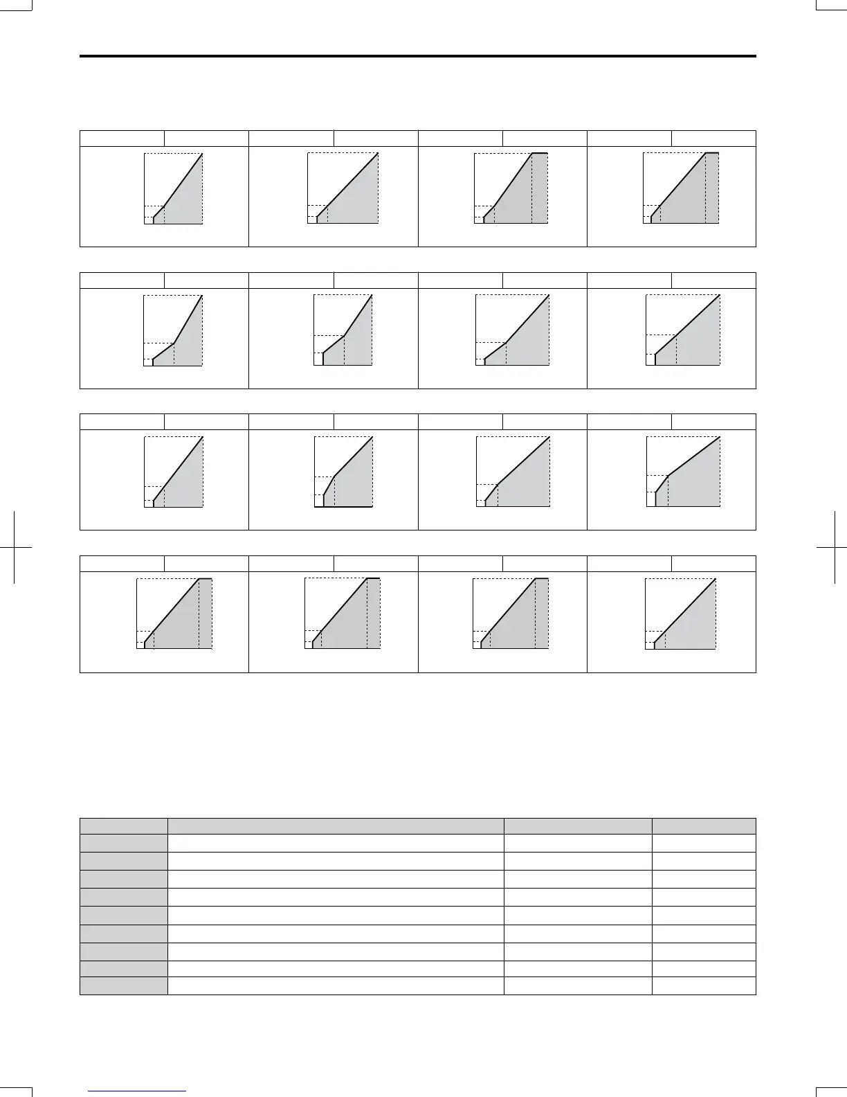
Predefined V/f Patterns for 4.0 to 15.0 kW Drives
The following graphs are for 200 V class drives. Double values when using a 400 V class drive.
Table 5.20 Rated Torque Characteristics, Settings 0 to 3
Setting = 0 50 Hz Setting = 1 60 Hz Setting = 2 60 Hz Setting = 3 72 Hz
0
7
200
1.3 2.5 50
14
Voltage (V)
Frequency (Hz)
0
7
14
200
1.5 3 60
Voltage (V)
Frequency (Hz)
Voltage (V)
Frequency (Hz)
0
7
14
200
1.5 3 6050
0
7
14
200
1.5 3 7260
Voltage (V)
Frequency (Hz)
Table 5.21 Derated Torque Characteristics, Settings 4 to 7
Setting = 4 50 Hz Setting = 5 50 Hz Setting = 6 60 Hz Setting = 7 60 Hz
Voltage (V)
Frequency (Hz)
0
6
200
1.3 25 50
35
0
7
200
1.3 25 50
50
Voltage (V)
Frequency (Hz)
Voltage (V)
Frequency (Hz)
0
6
200
1.5 30 60
35
0
7
200
1.5 30 60
50
Voltage (V)
Frequency (Hz)
Table 5.22 High Starting Torque, Settings 8 to B
Setting = 8 50 Hz Setting = 9 50 Hz Setting = A 60 Hz Setting = B 60 Hz
0
9
200
1.3 2.5 50
18
Voltage (V)
Frequency (Hz)
Voltage (V)
Frequency (Hz)
0
11
200
1.3 2.5 50
23
Voltage (V)
Frequency (Hz)
0
9
200
1.5 3 60
18
0
13
200
1.5 3 60
23
Voltage (V)
Frequency (Hz)
Table 5.23 Constant Output, Settings C to F
Setting = C 90 Hz Setting = D 120 Hz Setting = E 180 Hz Setting = F 60 Hz
0
7
14
200
1.5 3 9060
Voltage (V)
Frequency (Hz)
0
7
14
200
1.5 3 12060
Voltage (V)
Frequency (Hz)
0
7
14
200
1.5 3 18060
Voltage (V)
Frequency (Hz)
Voltage (V)
Frequency (Hz)
0
7
14
200
1.5 3 60
Setting a Custom V/f Pattern
Setting parameter E1-03 to “F” allows to set up a custom V/f pattern by changing parameters E1-04 to E1-13.
When E1-03 is changed to “F”, the default values for parameters E1-04 to E1-13 will be equal to V/f pattern 0 of the
predefined patterns.
n
V/f Pattern Settings E1-04 to E1-13
Using parameters E1-04 through E1-13, the user can either monitor the V/f pattern values if E1-03 =< 15 or set up a custom
V/f pattern as shown in Figure 5.40 when E1-03 = F.
No. Parameter Name Setting Range Default
E1-04 Maximum Output Frequency 40.0 to 400.0 Hz
<1>
,
<2>
E1-05 Maximum Voltage
0.0 to 255.0 V
<3> <1>
,
<2>
E1-06 Base Frequency 0.0 to 400.0 Hz
<1>
,
<2>
E1-07 Middle Output Frequency 0.0 to 400.0 Hz
<1>
E1-08 Middle Output Frequency Voltage
0.0 to 255.0 V
<3> <1>
E1-09 Minimum Output Frequency 0.0 to 400.0 Hz
<1>
,
<2>
E1-10 Minimum Output Frequency Voltage
0.0 to 255.0 V
<3> <1>
E1-11 Middle Output Frequency 2 0.0 to 400.0 Hz 0.0 Hz
E1-12 Middle Output Frequency Voltage 2
0.0 to 255.0 V
<3>
0.0 V
5.5 E: Motor Parameters
146
SIEP C710606 20 OYMC AC Drive - V1000 User Manual
7/16/2008-13:23