No. Name Setting Range Default
H3-01 Terminal A1 Signal Level Selection 0 to 1 0
Setting 0: 0 to 10 Vdc with Limit
The input level is 0 to 10 Vdc. Negative input values will be limited to 0.
Example: Terminal A1 is set to supply the frequency reference, and the bias (H3-04) is set to -100%. The frequency
reference can be set from 0 to 100% with an analog input of 5 to 10 V. The frequency reference will be zero when the
analog input is between 0 and 5 V.
0
10 V
100%
-100%
Analog input
voltage
Analog input
value
Negative input is limited to 0
Figure 5.65 Analog Input with Limit (Bias Setting -100%)
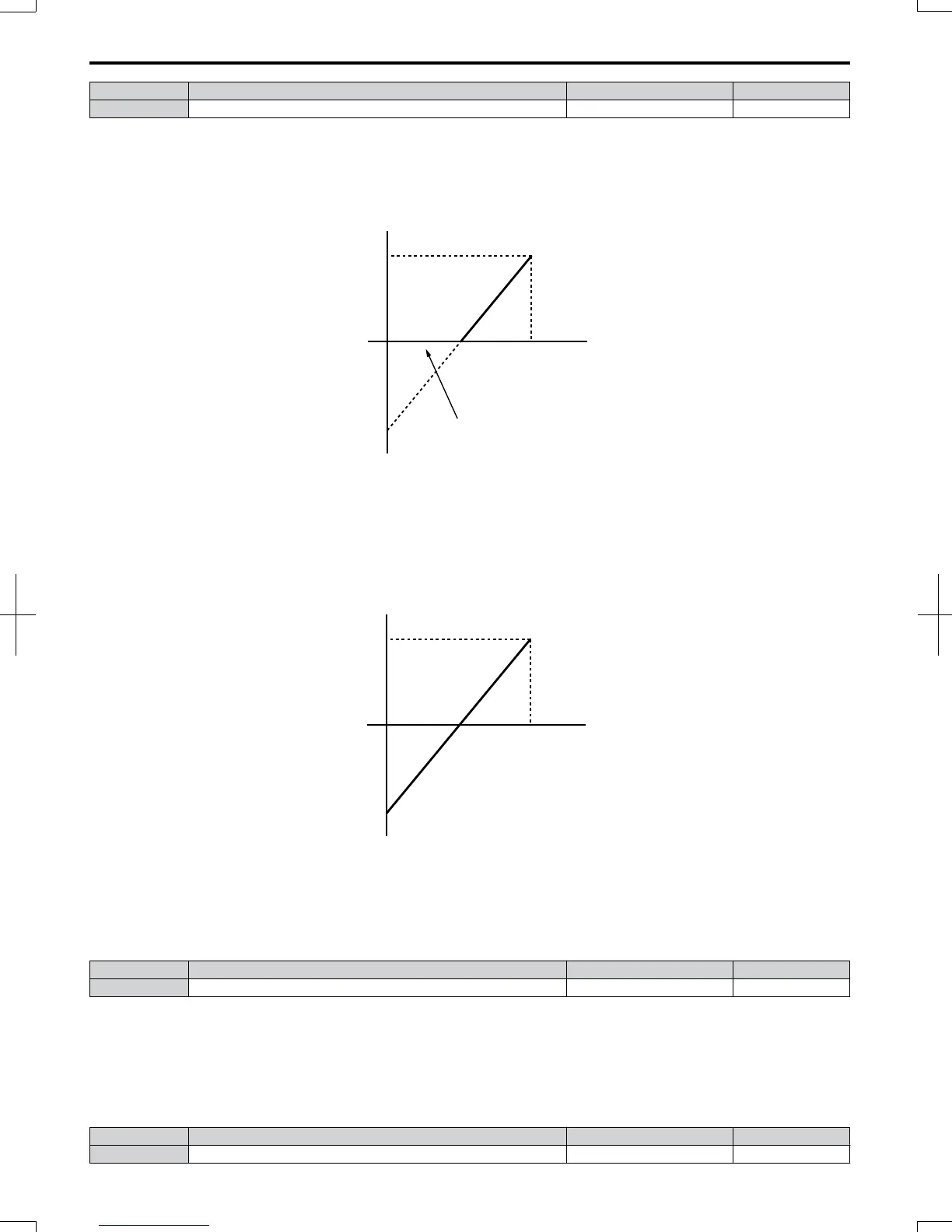
Setting 1: 0 to 10 Vdc without Limit
The input level is 0 to 10 Vdc. Negative input values will be accepted.
Example: Terminal A1 is set to supply the frequency reference, and the bias (H3-04) is set to -100%. The frequency
reference can be set from 0 to 100% with an analog input of 5 to 10 V. With an input of 0 to 5 V, the frequency reference
can be set from -100% to 0%. The drive reverses the motor rotation with negative input.
0V
10 V
100%
-100%
Analog input
voltage
Analog input
value
Figure 5.66 Analog Input without Limit (Bias Setting -100%)
n
H3-02: Terminal A1 Function Selection
Determines the function assigned to analog input terminal A1. Refer to Multi-Function Analog Input Terminal
Settings on page 180 for a list of functions and descriptions.
No. Name Setting Range Default
H3-02 Terminal A1 Function Selection 0 to 31 0
Note: If not using an input terminal or if using it in the through-mode, be sure to set that terminal to “F”.
n
H3-03/H3-04: Terminal A1 Gain/Bias Setting
Parameter H3-03 sets the level of the selected input value that is equal to 10 Vdc input at terminal A1 (Gain).
Parameter H3-04 sets the level of the selected input value that is equal to 0 V input at terminal A1.
Both can be used to adjust the analog input A1 characteristics.
No. Name Setting Range Default
H3-03 Terminal A1 Gain Setting -999.9 to 999.9% 100.0%
5.7 H: Terminal Functions
178
SIEP C710606 20 OYMC AC Drive - V1000 User Manual
7/16/2008-13:23