Setting 4: Operation with Reduced Speed
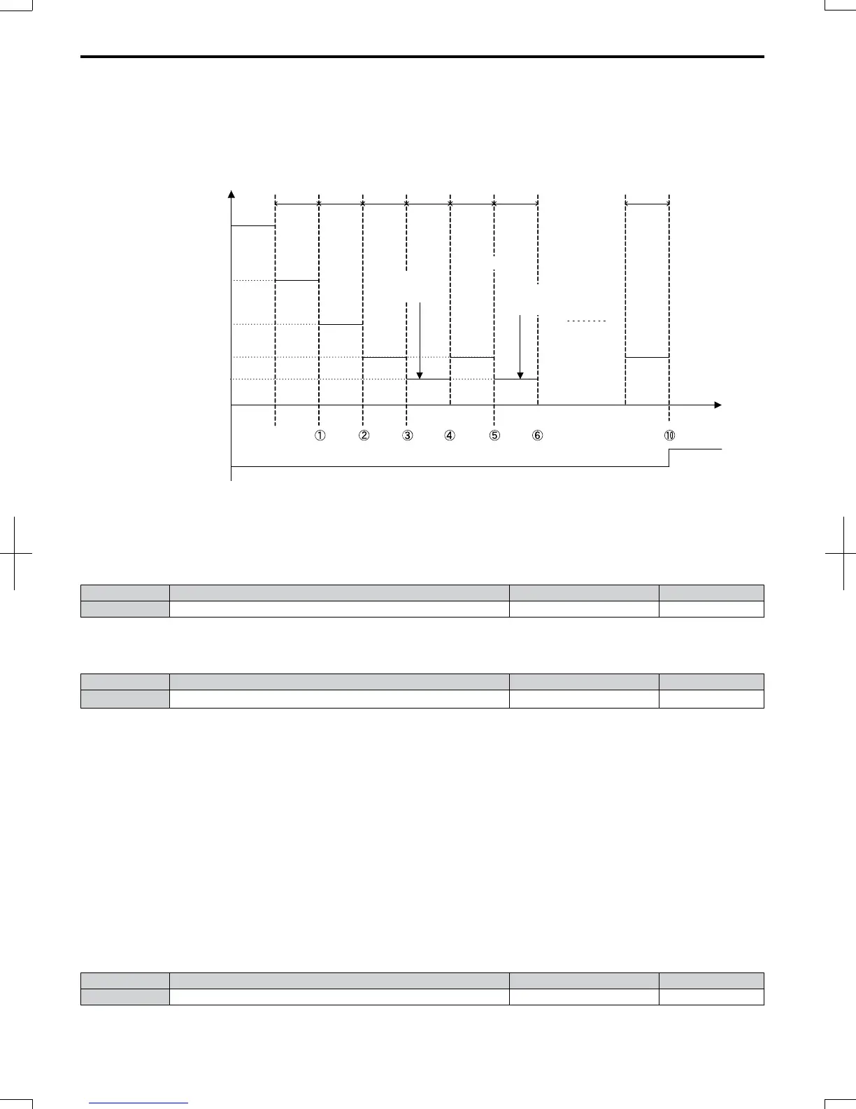
If an overheat alarm occurs, the operation is continued but the speed is reduced to the level set in parameter L8-19. If after
10 s the oH alarm is still present, the speed is reduced once more. The amount of reduction depends on how often the alarm
repeats. If the oH alarm disappears while the drive is operating at a reduced speed, then the drive will switch back to the
previous speed it was reduced to before. Figure 5.88 explains the operation with reduced speed during an oH alarm. A
digital output programmed for 4D is switched when the oH alarm is still active after ten reduction cycles.
10 s
etc.
time
10 s 10 s 10 s 10 s 10 s 10 s
f
ref
× (L8-19)
f
ref
× (L8-19)
2
f
ref
× (L8-19)
4
f
ref
× (L8-19)
3
f
ref
Output frequency
Reset oH
Alarm
Reset oH
Alarm
Digital ouput (4D)
oH
Alarm
oH
Alarm
oH
Alarm
oH
Alarm
oH alarm number
Figure 5.88 Output Frequency Reduction During Overheat Alarm
n
L8-19: Frequency Reduction Rate During Overheat Pre-Alarm
Specifies how much the output frequency is reduced when L8-03 is set to 4 and an oH alarm is present. Set as a factor of
the maximum output frequency.
No. Name Setting Range Default
L8-19 Frequency Reduction Rate During oH Pre-Alarm 0.1 to 0.9 0.8
n
L8-05: Input Phase Loss Protection Selection
Enables or disables the input phase loss detection.
No. Name Setting Range Default
L8-05 Input Phase Loss Detection Selection 0 or 1
1
<1>
<1> Disabled in 200 V single-phase drives.
Setting 0: Disabled
Setting 1: Enabled
Enables the input phase loss detection. As detection is performed by measuring the DC bus ripple, a phase loss fault (PF)
can also be triggered by power supply voltage imbalance or main circuit capacitor deterioration. Detection is disabled
when:
• The drive is decelerating.
• No Run command is active.
• Output current is less than or equal to 30% of the drive rated current.
n
L8-07: Output Phase Loss Detection
Enables or disables the output phase loss detection, which is triggered when the output current falls below 5% of the drive
rated current.
Note: Output phase loss detection can mistakenly be triggered if the motor rated current is very small compared to the drive rating. Disable this
parameter in such cases.
No. Name Setting Range Default
L8-07 Output Phase Loss Detection Selection 0 to 2 0
Setting 0: Disabled
5.8
L: Protection Functions
204
SIEP C710606 20 OYMC AC Drive - V1000 User Manual
7/16/2008-13:23