Cause Possible Solutions
Minor Fault
Output
(H2- = 10)
An external device has tripped an alarm
function.
Remove the cause of the external fault and reset the multi-function input value. YES
Wiring is incorrect.
• Ensure the signal lines have been connected properly to the terminals assigned for
external fault detection (H1- = 20 to 2F).
• Reconnect the signal line.
YES
Multi-function contact inputs are set
incorrectly.
•
Check if the unused terminals have been set for H1- = 20 to 2F (External Fault).
• Change the terminal settings.
YES
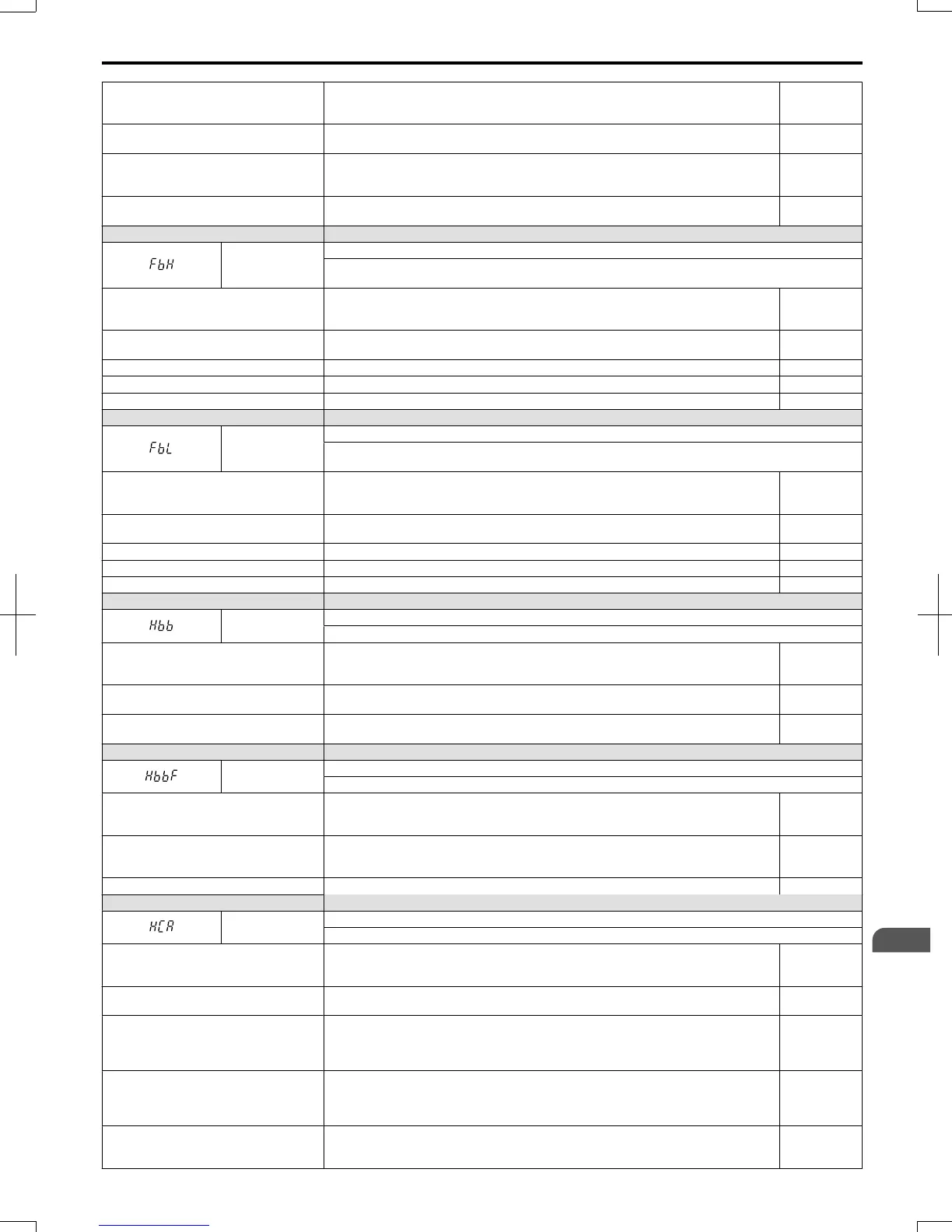
LED Operator Display Minor Fault Name
FbH
Excessive PID Feedback
The PID feedback input is higher than the level set in b5-36 for longer than the time set in b5-37, and
b5-12 is set to 1 or 4.
Cause Possible Solutions
Minor Fault
Output
(H2- = 10)
Parameters settings for b5-36 and b5-37 are
incorrect.
Check parameters b5-36 and b5-37. YES
PID feedback wiring is faulty. Correct the wiring. YES
Feedback sensor has malfunctioned. Check the sensor and replace it if damaged. YES
Feedback input circuit is damaged. Replace the drive. YES
LED Operator Display Minor Fault Name
FbL
PID Feedback Loss
The PID feedback input is lower than the level set in b5-13 for longer than the time set in b5-14, and
b5-12 is set to 1 or 4.
Cause Possible Solutions
Minor Fault
Output
(H2- = 10)
Parameters settings for b5-13 and b5-14 are
incorrect.
Check parameters b5-13 and b5-14. YES
PID feedback wiring is faulty. Correct the wiring. YES
Feedback sensor has malfunctioned. Check the sensor and replace it if damaged. YES
Feedback input circuit is damaged. Replace the drive. YES
LED Operator Display Minor Fault Name
Hbb
Safe Disable Signal Input
Both Safe Disable Input channels are open.
Cause Possible Solutions
Minor Fault
Output
(H2- = 10)
Both Safe Disable Inputs H1 and H2 are
open.
Check if external safety circuit tripped and disabled the drive. If the Safe Disable function
is not utilized, check if the terminals HC, H1, and H2 are linked.
YES
Internally, both Safe Disable channels are
broken.
Replace the drive. YES
LED Operator Display Minor Fault Name
HbbF
Safe Disable Signal Input
One of the Safe Disable input channels is open.
Cause Possible Solutions
Minor Fault
Output
(H2- = 10)
One of the inputs H1 and H2 is open when
the other is closed.
• Check the wiring to device that controls the Safe Disable inputs.
• If the Safe Disable function is not utilized, check that terminals HC, H1, and H2 are
linked properly.
YES
One of the Safe Disable channels is faulty. Replace the drive. YES
LED Operator Display Minor Fault Name
HCA
Current Alarm
Drive current exceeded overcurrent warning level (150% of the rated current).
Cause Possible Solutions
Minor Fault
Output
(H2- = 10)
Load is too heavy.
• Measure the current flowing through the motor.
• Reduce the load or increase the capacity of the drive.
YES
Acceleration and deceleration times are too
short.
• Calculate the torque required during acceleration and for the inertia moment.
• If the torque level is not right for the load, take the following steps:
• Increase the acceleration and deceleration times (C1-01 through C1-08).
• Increase the capacity of the drive.
YES
A special-purpose motor is being used, or
the drive is attempting to run a motor
greater than the maximum allowable
capacity.
• Check the motor capacity.
• Use a motor appropriate for the drive. Ensure the motor is within the allowable capacity
range.
YES
The current level increased due to Speed
Search after a momentary power loss or
while attempting to perform a fault restart.
The alarm will appear only briefly. There is no need to take action to prevent the alarm
from occurring in such instances.
YES
6.5 Alarm Detection
SIEP C710606 20 OYMC AC Drive - V1000 User Manual
243
6
Troubleshooting
7/16/2008-13:23