No. Name Description Range Def.
Control
Mode
Addr.
Hex
Pg.
V/f
O
LV
P
M
L6-08
Mechanical Weakening
(oL5) Detection Operation
This function can detect an over/undertorque in a certain
speed range as a result of machine fatigue. It is triggered by
a certain operation time and uses the oL1 detection settings
(L6-01 to L6-02)
0: Mechanical Weakening Detection disabled.
1: Continue running (alarm only). Detected when the speed
(signed) is greater than L6-09.
2: Continue running (alarm only). Detected when the speed
(not signed) is greater than L6-09.
3: Interrupt drive output (fault). Detected when the speed
(signed) is greater than L6-09.
4: Interrupt drive output (fault). Detected when the speed (not
signed) is greater than L6-09.
5: Continue running (alarm only). Detected when the speed
(signed) is less than L6-09.
6: Continue running (alarm only). Detected when the speed
(not signed) is less than L6-09.
7: Interrupt drive output (fault). Detected when the speed
(signed) is less than L6-09.
8: Interrupt drive output (fault). Detected when the speed (not
signed) is less than L6-09.
0 to 8 0 A A A 468 201
L6-09
Mechanical Weakening
Detection Speed Level
Sets the speed that triggers mechanical weakening detection.
When L6-08 is set for an unsigned value, the absolute value
is used even if the setting is negative.
-110.0 to
+110.0%
110% A A A 469 202
L6-10
Mechanical Weakening
Detection Time
Sets the time a mechanical weakening has to be detected
before an Alarm/Fault is triggered.
0.0 to 10.0
s
0.1 s A A A 46A 202
L6-11
Mechanical Weakening
Detection Start Time
Sets the operation time (U1-04) that has to be passed before
Mechanical weakening detection is active.
0 to 65535 0 A A A 46B 202
L7: Torque Limit
Use L7 parameters to configure the torque limit function.
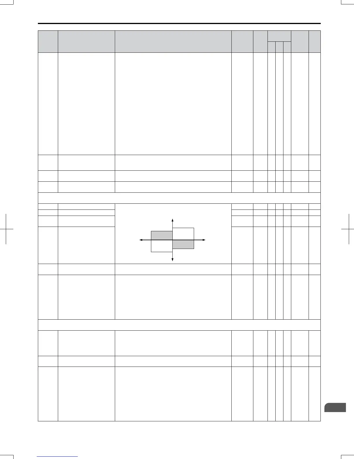
L7-01 Forward Torque Limit Sets the torque limit value as a percentage of the motor rated
torque. Four individual quadrants can be set.
L7-01
L7-03
L7-02
L7-04
output torque
positive torque
REV
negative torque
FWD
motor
r/min
regeneration
regeneration
0 to 300 200% − A − 4A7 202
L7-02 Reverse Torque Limit 0 to 300 200% − A − 4A8 202
L7-03
Forward Regenerative
Torque Limit
0 to 300 200% − A − 4A9 202
L7-04
Reverse Regenerative
Torque Limit
0 to 300 200% − A − 4AA 202
L7-06
Torque Limit Integral Time
Constant
Sets the integral time constant for the torque limit. 5 to 10000
200
ms
− A − 4AC 202
L7-07
Torque Limit Control
Method Selection during
Accel/Decel
Selects the method of torque limit control during accel/decel.
0: Proportional Control (change to integral controls at fixed
speeds). Use this setting when acceleration to the desired
speed has priority over torque limitation.
1: Integral Control. Use this setting if the torque limitation
has priority.
When torque limit is applied to the motor, accel/decel time
may increase and motor speed may not meet the speed
reference.
0, 1 0 − A − 4C9 203
L8: Hardware Protection
Use L8 parameters to configure hardware protection functions.
L8-01
Internal Dynamic Braking
Resistor Protection Selection
(ERF type)
Selects the Braking resistor when using a 3% duty cycle
heatsink mounted braking resistor. This parameter does not
enable or disable the braking transistor of the drive.
0: Resistor overheat protection disabled
1: Resistor overheat protection enabled
0,1 0 A A A 4AD 203
L8-02 Overheat Alarm Level
When the heatsink temperature exceeds the value set in this
parameter, an Overheat Alarm (oH) will occur.
50 to 130
<12>
A A A 4AE 203
L8-03
Overheat Pre-Alarm
Operation Selection
Sets the drive operation when an overheat alarm oH is
detected.
0: Ramp to Stop using the active decel time.
1: Coast to Stop.
2: Fast-stop using the time set in C1-09.
3: Alarm Only. Drive continues running, but displays an
alarm.
4: Reduced Speed Operation. Drive continues to run with
reduced frequency reference as specified in L8-19.
Settings 0 through 2 trigger a fault relay if the heatsink
becomes too hot.
0 to 4 3 A A A 4AF 203
B.2 Parameter Table
SIEP C710606 20 OYMC AC Drive - V1000 User Manual
325
B
Parameter List
7/16/2008-13:23