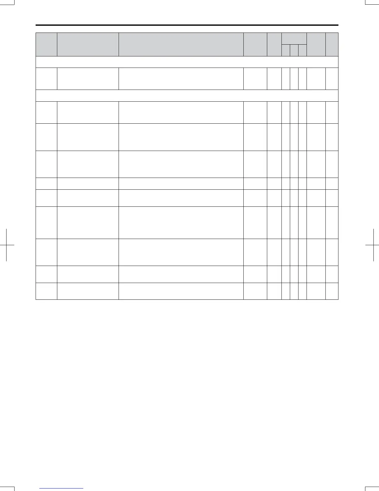
No. Name Description Range Def.
Control
Mode
Addr.
Hex
Pg.
V/f
O
LV
P
M
n6: Online Tuning of Motor Line-to-Line Resistance
Use n6 parameters to adjust the motor line-to-line resistance while the drive is online.
n6-01
Line-to-Line Motor
Resistance Online Tuning
Tunes the line-to-line motor resistance continuously during
operation.
0: Disabled
1: Enabled
0, 1 1 − A − 570 210
n8: Permanent Magnet (PM) Motor Control
Use n8 parameters to control the PM motor control.
n8-45
Speed Feedback Detection
Control Gain
Sets the gain for internal speed feedback detection control.
This parameter does not typically require adjustment.
Increase this setting if hunting occurs.
Decrease to lower the response.
0.0 to 10.0 0.8 − − A 538 211
n8-47
Pull-In Current
Compensation Time
Constant
Sets the time constant to make the pull-in current and actual
current value agree.
Decrease the value if the motor begins to oscillate.
Increase the value if it takes too long for the current reference
to equal the output current.
0.0 to
100.0 s
5.0 s − − A 53A 211
n8-48 Pull-In Current
Defines the amount of current provided to the motor during
no-load operation at a constant speed.
Set as a percentage of the motor rated current. Increase this
setting when hunting occurs while running at a constant
speed.
20 to
200%
30% − − A 53B 211
n8-49 Load Current
Sets the amount of d-axis current when using Energy Saving
control.
-200.0 to
0.0%
0% − − A 53C 211
n8-51 Acceleration Pull-In Current
Sets the pull-in current during acceleration as a percentage of
the motor rated current (E5-03). Set to a high value when
more starting torque is needed.
0 to 200% 50% − − A 53E 211
n8-54
Voltage Error Compensation
Time Constant
Sets the time constant for voltage error compensation. Adjust
the value when
hunting occurs at low speed.
hunting occurs with sudden load changes. Increase in steps
of 0.1 or disable the compensation by setting n8-45 to 0.
oscillations occur at start. Increase the value in steps of 0.1.
0.00 to
10.00 s
1.00 s − − A 56D 211
n8-55 Load Inertia
Sets the ratio between motor and machine inertia.
0: less than 1:10.
1: between 1:10 to 1:30.
2: between 1:30 to 1:50.
3: higher than 1:50.
0 to 3 0 − − A 56E 211
n8-62
<24>
Output Voltage Limit
Sets the limit for the output voltage. Adjustment is normally
needed only if the input voltage is below the n8-62 set value.
In this case set n8-62 to the input voltage.
0.0 to
230.0
200
Vac
- - A 57D 212
n8-65
<59>
Speed Feedback Detection
Control Gain during ov
Suppression
Sets the gain used for internal speed feedback detection
during ov Suppression
0.00 to
10.00
1.50 - - A 65C 212
<12> Default setting value is dependent on parameter o2-04, Drive Model Selection.
<24> Values shown here are for 200 V class drives. Double the value when using a 400 V class drive.
<59> Available in drive software 1011 and later.
B.2 Parameter Table
328
SIEP C710606 20 OYMC AC Drive - V1000 User Manual
7/16/2008-13:23