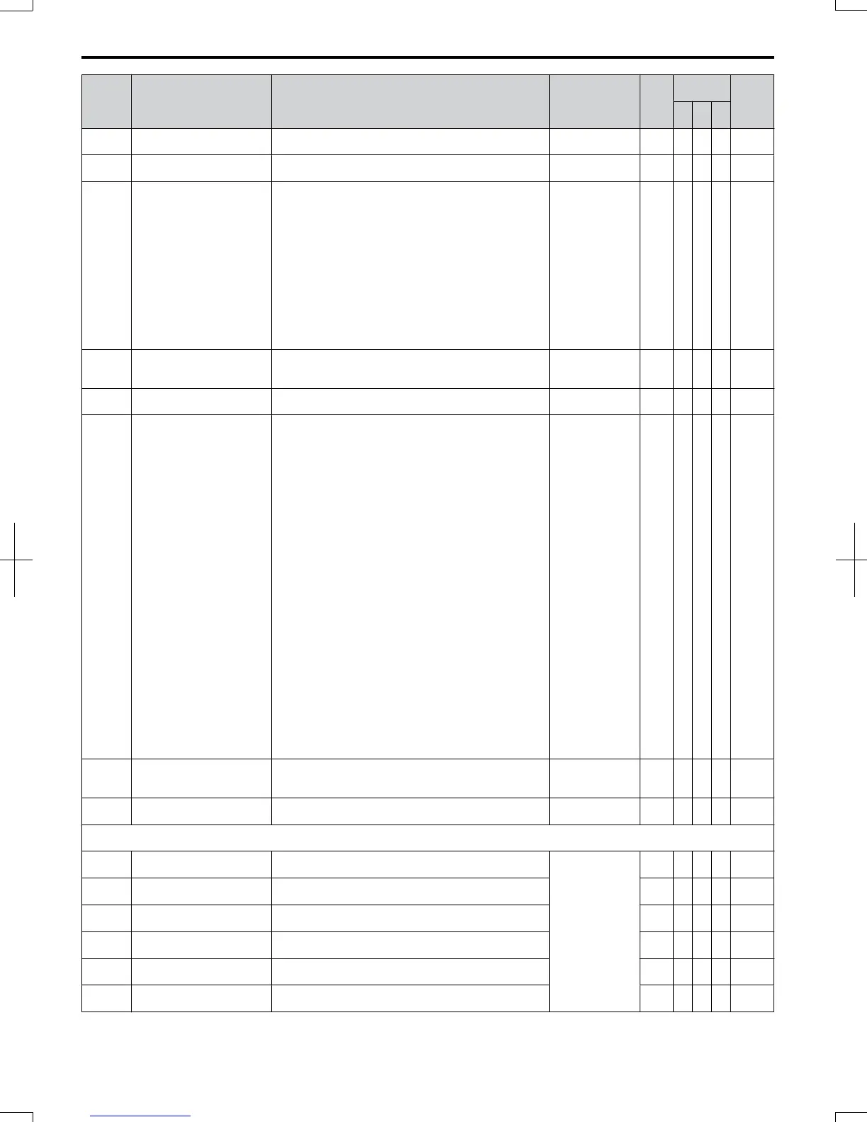
No. Name Description
Analog Output
Level
Unit
Control
Mode
Addr.
Hex
V/f
O
LV
P
M
U4-14 Peak Hold Output Frequency
Displays the output frequency when operating at the peak
hold current.
10 V: Max
frequency
0.01H
z
A A A 7D0
U4-16
Motor Overload Estimate
(oL1)
100% = oL1 detection level
100% = oL1
detection level
0.1% A A A 7D8
U4-18
Frequency Reference Source
Selection
Displays the source for the frequency reference as XY-nn.
X: indicates which reference is used:
1 = Reference 1 (b1-01)
2 = Reference 2 (b1-15)
Y-nn: indicates the reference source
0-01 = Operator (d1-01)
1-01 = Analog (terminal A1)
1-02 = Analog (terminal A2)
2-02 to 17 = Multi-step speed (d1-02 to 17)
3-01 = MEMOBUS/Modbus comm.
4-01 = Option
5-01 = Pulse Input
6-01 = CASE
7-01 = FDBs
– – A A A 7DA
U4-19
Frequency Reference from
MEMOBUS/Modbus
Comm.
Displays the frequency reference provided by MEMOBUS/
Modbus (decimal).
– – A A A 7DB
U4-20 Option Frequency Reference
Displays the frequency reference input by an option card
(decimal).
– – A A A 7DD
U4-21
Run Command Source
Selection
Displays the source for the Run command as XY-nn.
X: Indicates which Run source is used:
1 = Reference 1 (b1-02)
2 = Reference 2 (b1-16)
Y: Input power supply data
0 = Operator
1 = External terminals
2 = Not used
3 = MEMOBUS/Modbus communications
4 = Option
5 = Not used
6 = CASE
7 = FDBs
nn: Run command limit status data
00: No limit status.
01: Run command was left on when stopped in the PRG
mode.
02: Run command was left on when switching from
LOCAL to REMOTE operation.
03: Waiting for the soft charge bypass contactor after the
power is switched on (Uv or Uv1 flashes after 10 seconds).
04: Waiting for “Run Command Prohibited” time period to
end.
05: Fast-stop (digital input (H1- = 15), operator)
06: b1-17 (run command given at power-up).
07: During Baseblock while coast to stop with timer
08: Frequency reference is below minimal reference during
Baseblock
09: Waiting for Enter command
A A A 7DD
U4-22
MEMOBUS/Modbus
Communications Reference
Displays the drive control data set by MEMOBUS/Modbus
communications register No. 0001H as a 4 digit
hexadecimal number.
— — A A A 7DE
U4-23 Option Card Reference
Displays drive control data set by an option card as a 4 digit
hexadecimal number.
— — A A A 7DF
U5: PID Monitor
Use U5 parameters to view application-specific settings.
U5-01 PID Feedback Displays the PID feedback value in.
10 V: 100% (max.
freq.)
0.01
%
A A A 57
U5-02 PID Input
Displays the amount of PID input (deviation between PID
target and feedback).
0.01
%
A A A 63
U5-03 PID Output Displays PID control output.
0.01
%
A A A 64
U5-04 PID Setpoint Displays the PID setpoint.
0.01
%
A A A 65
U5-05 PID Differential Feedback
Displays the 2nd PID feedback value if differential
feedback is used.
0.01
%
A A A 7D2
U5-06 PID Adjusted Feedback
Displays the subtraction value of both feedback values if
differential feedback is used.
0.01
%
A A A 7D3
B.2 Parameter Table
336
SIEP C710606 20 OYMC AC Drive - V1000 User Manual
7/16/2008-13:23