<1> Remove the jumper when installing an optional DC reactor.
<2> The MC on the input side of the main circuit should open when the thermal relay is triggered.
<3> Self-cooled motors do not require separate cooling fan motor wiring.
<4> Connected using sequence input signal (S1 to S6) from NPN transistor; Default: sink mode (0 V com).
<5> Use only a +24 V internal power supply in sinking mode; the source mode requires an external power supply Refer
to I/O Connections on page 55.
<6> Monitor outputs work with devices such as analog frequency meters, ammeters, voltmeters and wattmeters; they
are not intended for use as a feedback-type of signal.
<7> Disconnect the wire jumper between HC, H1, and H2 when utilizing the safety input.Refer to Wiring Procedure
on page 52 for details on removing the jumper. The wire length for the Safe Disable input should not exceed 30
m.
WARNING! Sudden Movement Hazard. Do not close the wiring for the control circuit unless the multifunction input terminal parameter
is properly set (S5 for 3-Wire; H1-05 = “0”). Improper sequencing of run/stop circuitry could result in death or serious injury from moving
equipment.
WARNING! Sudden Movement Hazard. Ensure start/stop and safety circuits are wired properly and in the correct state before energizing
the drive. Failure to comply could result in death or serious injury from moving equipment. When programmed for 3-Wire control, a
momentary closure on terminal S1 may cause the drive to start.
WARNING! When 3-Wire sequence is used, set the drive to 3-Wire sequence before wiring the control terminals and ensure parameter
b1-17 is set to 0 (drive does not accept a run command at power up (default). If the drive is wired for 3-Wire sequence but set up for 2-
Wire sequence (default) and if parameter b1-17 is set to 1 (drive accepts a Run command at power up), the motor will rotate in reverse
direction at power up of the drive and may cause injury.
WARNING! When the application preset function is executed (or A1-06 is set to any value other than 0) the drive I/O terminal functions
change. This may cause unexpected operation and potential damage to equipment or injury.
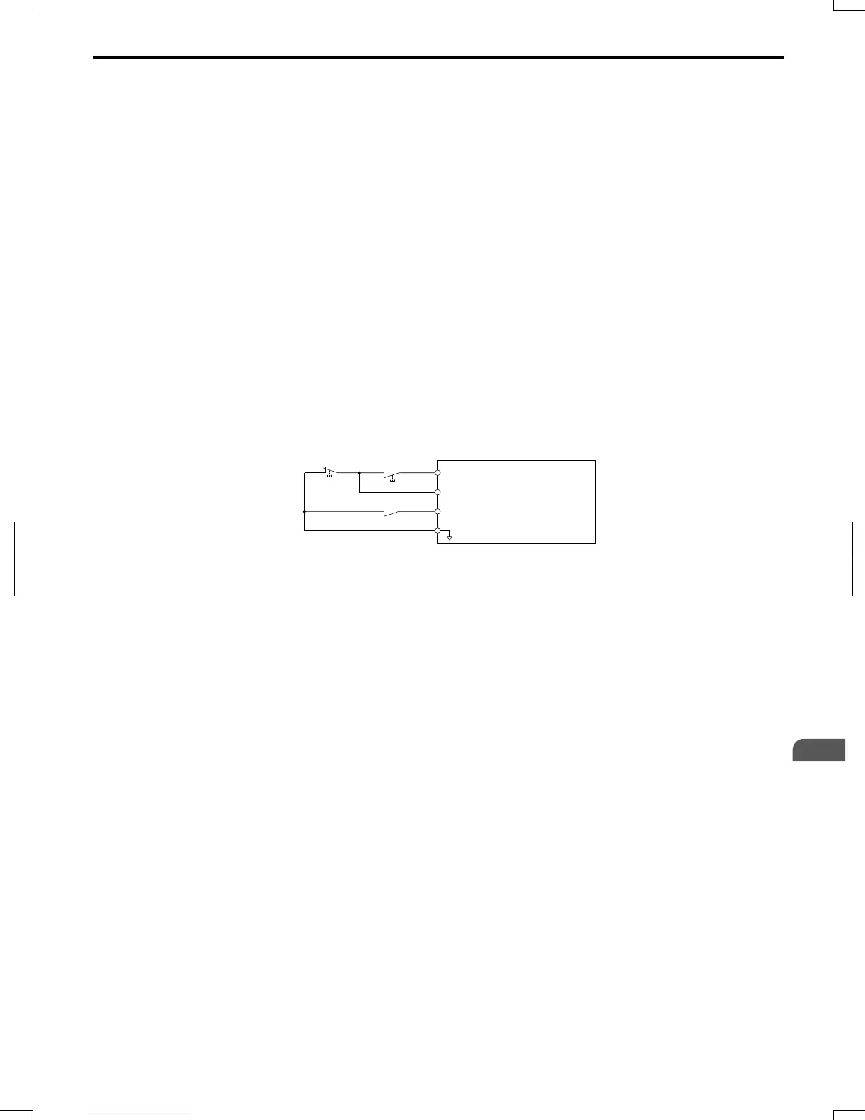
Figure 3.2 illustrates an example of a 3-Wire sequence.
Drive
Sequence input common
Run relay (N.O.)
Stop relay (N.C.)
Run command (run on momentary close)
Stop command (stop on momentary open)
Foward/reverse command
(multi-function input: H1-05 = 0)
S1
S2
S5
SC
Figure 3.2 3-Wire Sequence
3.2 Standard Connection Diagram
SIEP C710606 20 OYMC AC Drive - V1000 User Manual
41
3
Electrical Installation
7/16/2008-13:23