Operation
30 900-0117-01-00 Rev B
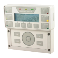
LED Status Indicators
Battery LEDs
Three LEDs provide a visual reference to indicate the condition of the battery bank.
A GREEN LED means the batteries have an adequate charge at that time. It does not always mean they are full. If
an FNDC is installed, this means the batteries are
80%
State of Charge (SOC).
A YELLOW LED means the batteries are somewhat discharged. If an FNDC is installed, this means the batteries
are
60%
and
70%
.
A RED LED means the batteries are greatly discharged and may require attention. If an FNDC is installed, this
means the batteries are
< 60%
. May be accompanied by an event indicator and a
Low Battery V
error. (See
pages
14
31 and
14
43.)
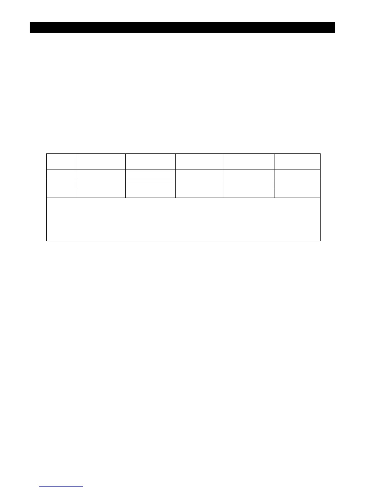
Table 2 Battery Status LEDs
Color 12 Vdc Unit
24 Vdc Unit,
± 0.2 Vdc
36 Vdc Unit,
± 0.3 Vdc
48 Vdc Unit,
± 0.4 Vdc
Battery Status
GREEN 12.5 Vdc or higher 25.0 Vdc or higher 37.5 Vdc or higher 50.0 Vdc or higher ACCEPTABLE
YELLOW 11.5 to 12.4 Vdc 23.0 to 24.8 Vdc 34.5 to 37.2 Vdc 46.0 to 49.6 Vdc USABLE
RED 11.4 Vdc or lower 22.8 Vdc or lower 34.2 Vdc or lower 45.6 Vdc or lower LOW
NOTES:
Gaps in the table (higher-voltage units) are due to the resolution of the inverter’s DC meter.
These voltage settings are not the same as the inverter’s Low Battery Cut-Out voltage. (See page
14
85.)
The Battery LED settings cannot be changed.
Voltages higher than shown in the GREEN row usually means that the batteries are charging.
Inverter LED (green)
This LED is located on the
INVERTER
hot key. (See page
14
55.) It provides a visual reference for the status
of the inverter operation.
ON
(solid) — inverter is converting DC to AC in order to power loads.
ON
(flashing) — the inverter is in Search mode.
OFF
(not illuminated)
~ the inverter is not converting DC power to AC power, or
~ the AC input source is powering the loads.
In stacked configurations, the master inverter controls this LED status. If any inverters in a stacked system
have a different inverting status from the master, this LED will not display their status.
Charger LED (yellow)
This LED is located on the
CHARGER
hot key. (See page
14
56.) It provides a visual reference for the status
of the battery charger.
ON
(illuminated) — a device on the HUB is delivering more than a minimal amount of charging power. The
device may be an inverter or a charge controller.
ON
(flashing) — the batteries are being equalized.
OFF
(not illuminated) — no device is actively charging the batteries, for several reasons.
~ the charger(s) may be functional, but in a quiescent state such as Silent.
~ the charger(s) may be functional, but the charging sources may be disconnected or unavailable.
~ the charger(s) may be turned off.