106 EVO Installation Guide
Appendix C: Keypad Installation Instructions
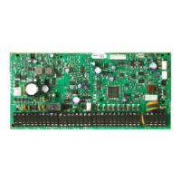
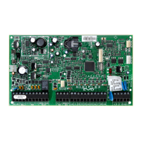
Connecting the Keypads
The keypads are connected to the control panel's combus in a star and/or daisy chain configuration. Connect
the four terminals labeled red, black, green and yellow of each keypad to the corresponding terminals on the
control panel.
Connecting Keypad Zones
Each keypad has one hardwired input terminal, allowing you to connect one detector or door contact directly
to it. Connect the device to the keypad's input terminal. In order to communicate its status to the control panel,
the keypad's input must be assigned to a zone in the control panel and the zone's parameters must be defined.
Programmable Output
Each keypad has one on-board PGM. Upon activation, the PGM can provide 50mA to any device connected to
it. If the current drawn is to exceed the current limit, a relay should be connected to the PGM.
Keypad Specific Instructions
C.0.1 Memory Key Connection
A memory key can be used to download programming to the K641 and K641R keypads.
C.0.2 Memory Key
SECTIONS [510] AND [520]
Download information using the memory key (PMC-4).
C.0.3 Download Contents of Memory Key to Keypad
SECTION [510]
1. Insert the memory key into the keypad’s connector labelled “KEY.”
2. To download the contents of the memory key, enter the keypad’s programming mode and enter section
[510].
3. When the keypad emits a confirmation beep, wait 5 seconds and remove the memory key after the second
confirmation beep.
C.0.4 Copy the Keypad Contents to the Memory Key
SECTION [520]
1. Insert the memory key onto the keypad’s connector labelled “KEY.” Ensure that the write protect jumper is
ON.
2. To copy the contents to the memory key, enter the keypad’s programming mode and enter section [520].
Section [510] =
Download all from the memory key (LCD keypad
sections [001] to [396] and all messages) to the LCD
keypad.
Section [520] =
Copy the LCD keypad sections [001] to [396] and all
messages to the memory key.