EVO Installation Guide 25
2.21.1 Connecting the Combus in Noisy Environments
When installing the combus wires in proximity to high electrical interferences or across separate buildings, use
shielded cables:
Within the Same Building: Strip the outer jacket at one end of the shielded cable to expose the shield and
connect the shield to the control panel ground (not the dialer ground), while leaving the shield at the other end
of the cable open (floating).
Across Separate Buildings: Strip the outer jacket at one end of the shielded cable to expose the shield. In the
same building as the control panel, connect the exposed shield to any earth ground available, while leaving the
shield at the other end of the cable open (floating). The same configuration applies for any subsequent
building.
2.22 Fire Circuits
Assign the smoke detectors connected to the control panel or zone expansion input terminals to a zone and
define the zone's parameters as a Fire Zone (
see section 4.4.12 and see section 4.4.13 on page 35).
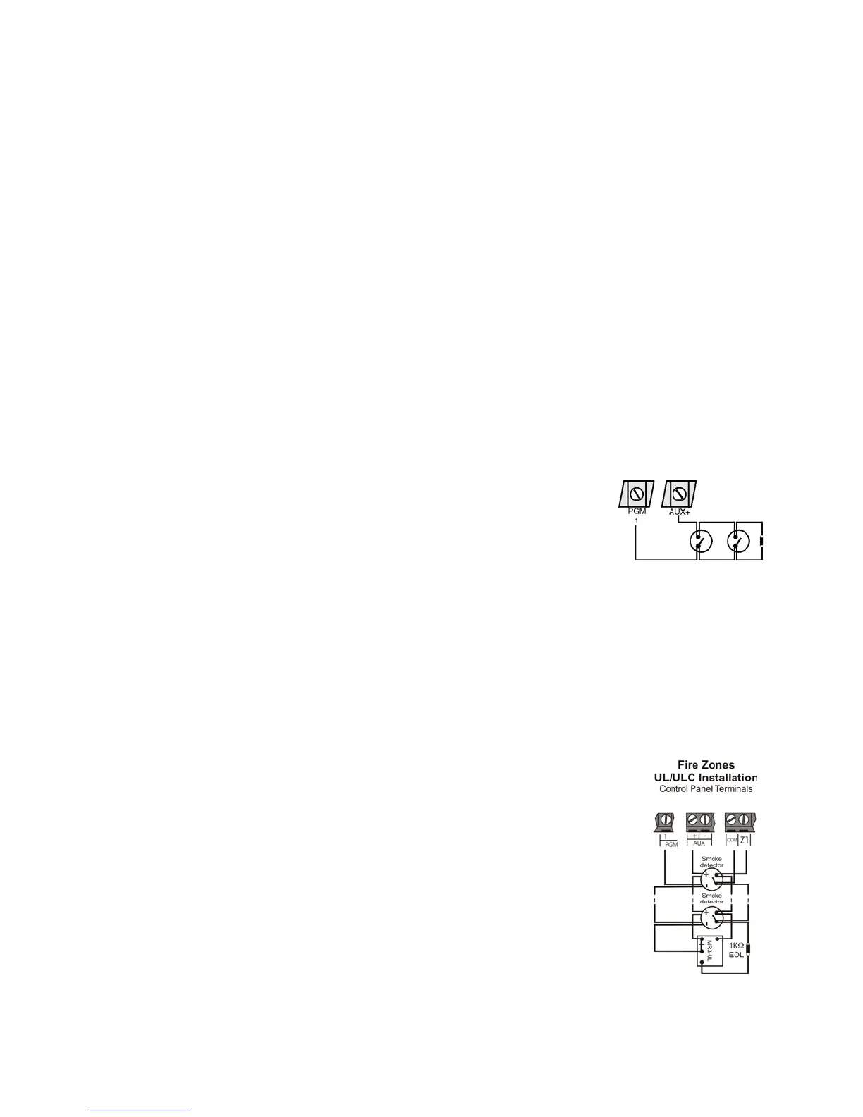
2.22.1 Smoke Detector Installation (2-Wire)*
PGM1 can be defined as a 2-wire smoke detector input (see ). Connect the 2-wire
smoke detectors as shown in
Figure 8. If a line short occurs or the smoke detector
activates, whether the system is armed or disarmed, the control panel will generate
an alarm. If the line is open, the “Zone Fault” trouble indication appears in the
Trouble Display and the report code is sent to the monitoring station, if
programmed.
*
UL Note: Not to be used with UL Listed systems.
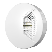
2.22.2 ESL CleanMe
®
Installation
Connect ESL smoke detectors like the standard smoke detectors. Avoid connecting more than 20 ESL smoke
detectors. When a CleanMe signal is sent, the control panel will generate a Zone Fault trouble and may transmit
the Fire Loop report code to the monitoring station. The trouble will be cleared if there is no CleanMe signal for
255 seconds. If an alarm occurs, the trouble will be cleared until it is detected again.
2.22.3 Smoke Detector Installation (4-Wire)
Recommended: System Sensor model 2112/24D smoke detectors. Connect the 4-
wire smoke detectors and a relay as shown in Figure 9. To comply with UL955, install
the 4-wire smoke detectors with 18 gauge wire. If power is interrupted, the relay
causes the control panel to transmit the Fire Loop Trouble report programmed in
section
[2906].
To reset (unlatch), connect the smoke detector’s negative (-) to a PGM. Then program
the PGM with the “Smoke Detector Power Reset” activation event (; Event Group
#067, start # 004, end # 004) to interrupt power to the smoke detector for four
seconds when the
[CLEAR] and [ENTER] keys are pressed and held for two seconds.
In order to enable “Fire Alarm Verification” go to section [3028] and set option [4] to
Enable.
Note: The 2-wire smoke detector is not UL approved.
Figure 8:
2-Wire Detectors
Note: It is recommended that the smoke
detectors be connected in a daisy chain
configuration.
PGM1 becomes
input# 255
Smoke detectors
1KW
EOL
N.O. contacts
Figure 9: 4-Wire Detectors
Note: It is recommended that the
smoke detectors be connected in a
daisy chain configuration.