.
MEM KEY
SERIAL
RED
BLK
COM
BELL
AC AC
AUXRELAY
GRN
YEL
+
BUS
Z1 Z2
Z3
Z4 Z5 Z6 Z7 Z8 R-1 T-1 RING TIP
COM COM
COM
+
–
–
PARADOX
SECURITY SYSTEMS
D I G I P L E X
E
V
O
DIALER
EBUS
SERVICE
KEYPAD
BATT
N.C.N.O.
12 3
4
PGM
RED
BLK
GRN
YEL
KEYPAD
PGM
Z1
RED
BLK
GRN
YEL
DETECTOR
RED
BLK
GRN
YEL
ANY MODULE
STATUS
AUX
AUX
COMBUS
120VAC/
17VAC
transformer
UL
120VAC/
17VAC
transformer
CAN
+–
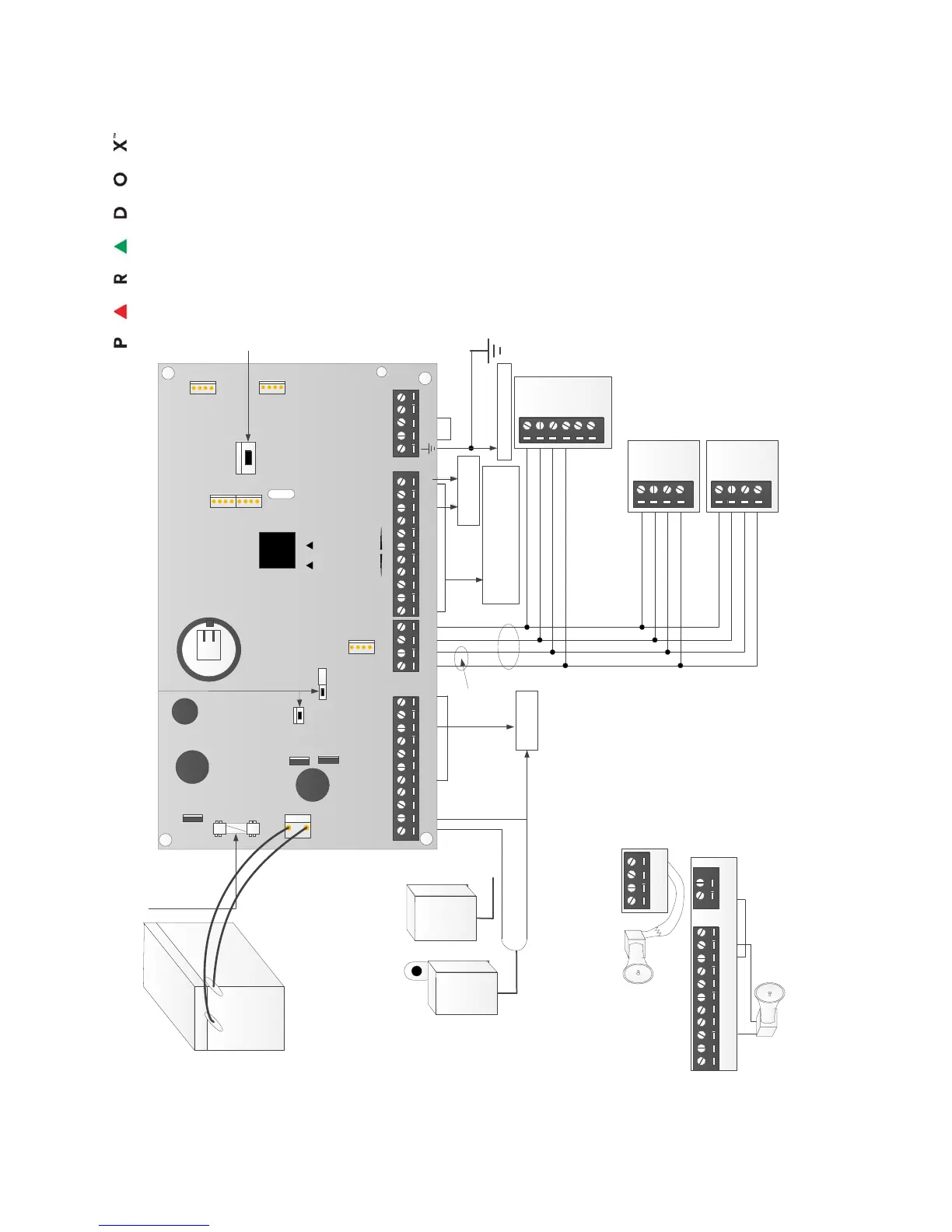
Transformer Requirements: 120VAC/17VAC , 40VA
Auxiliary Supply can provide: max. 700mA
Automatic Shut Down 1.1a
Usable Battery Charge Currents: 850mA max.
Caution: Disconnect the battery
before replacing the fuse.
The "BELL" output will
shutdown if the current
exceeds 3A.
*A 1 KU resistor is required
if the Bell is not equipped
with an internal resistor.
Position the resistor as
close as possible to the
Bell. A resistor is not
required for sirens.
SELF-CONTAINED BELL/
SIREN
To metalic enclosure
Red “STATUS” LED
Flashing – indicates proper
operation
Always on – panel is using a
phone lilne
Fast Flash – indicates a control
panel failure
Off – Control panel error
The COMBUS supports a maximum of 254 (EVO192)
modules.
Although external power supplies can be used to provide
power to modules connected far from the control panel
the total distance of all runs of wire combined cannot
exceed 914m (3000 ft.). For example if ten runs of wire
measuring 305m (1000 ft.) each are connected to the
control panel, the total distance would be 3048m (10000
ft.) which exceeds the system capacity.
Before adding any modules to the control panel make sure
you shut down the AUX output by pressing and holding the
AUX button for 3 seconds.
Please Note: When powering up the EVO control panel ,
the panel will begin a module scan to verify that all
modules connected to the panel are operational. The
scanning process will take between 30 seconds and 3
minutes to complete depending on the number of
modules connected to the control panel. The module
scan is complete when the LCD keypad begins to show
the partition status. Only after the module scan is
completed will the control panel be fully operational.
When Installing the combus wires in a noisy environment
or when connecting the combus across separate
buildings, you must use a shielded cable. Refer to section
2.15.1.
Please see ETL and ETLC Warnings for and information
in the appendix.
Auxiliary supply
can provide:
Max. 700 mA
AWG#14 single conductor
solid copper wire
AUX LED and AUX control button
Activates and deactivates the auxiliary output
12Vdc 7Ah Rechargeable
Lead-Acid backup battery
(3) For hardwired connections see
single zone and double zone
connections.
Wiring methods that shall be in accordance with the National Electrical
Code, ANSI/NFPA 70, the Standard for Installation and Classification of
Burglar and Holdup Alarm Systems, UL 681, and the Standard for Central-
Station Alarm Services, UL 827.
Do not short the terminals of the transformer together. This causes the internal fuse to blow.
The transformer must be connected to a 230 VAC, 24-hour outlet not controlled by a switch
other than an approved over-current protection device.
For continued protection against risk of fire, replace fuses only with fuses of the same type
and rating.
The system should be installed in accordance with Chapter
2 of the National Fire Alarm Code, ANSI/NFPA 72
The metal housing which enclosed the Fire and Burglary system housing
has knockouts on the sides and in the back enclosure. The wiring
method requires that bushings are used for wiring through the metal
box. Including the transformer with Plug in Power Supply.
WARNING: To prevent risk of electric shock, disconnect
AC battery and phone cord BEFORE Servicing.
All knockouts provided for connection of a field-wiring system to a field-
wiring compartment shall accommodate conduit of the trade size according
to NEC.
Intended wiring methods must be in keeping with the requirements of CSA
C22.1, Canadian Electrical Code, Part I, Safety Standard for Electrical
Installations.
(2)
1. ETL note: Use an ETL/UL approved bell/siren
2. Wiring conventions have to be in the same room of these terminals
3. Zone Input Specifications: Maximum loop current (shorted loop): 2.2 mA
Maximum loop voltage (open loop): 5.0 VDC
4. Disconnect Telecom jack before servicing
5. The anti-tamper switch needs to be connected to a separate zone configured for 24 hrs
6. For Maximum number of devices to be employed refer to the Features in section 1.1
7. The minimum permissible wire size to be employed shall be not smaller than No. 22 AWG (0.32 mm2).
BELL
AC AC
+
–
BELL
AC AC
RELAY
COM
+
–
N.C.N.O.
12 3
4
PGM
Z1
COM
The sum total of the current draw from the bell/siren and the AUX must be
llimitted to 2.0A. Exceeding this limit will overload the panel power supply and
lead to complete system shutdown.
Notes:
(4)
(1)
For US: UL/ETL Listed
Class 2 wall/building
120VAC/60Hz power
supply with
restraining means.
For Canada: CSA/ULc/
ETLc Listed Class 2
Power Supply with NO
restraining means.
To power-on
switch
(5) To anti-
tamper switch
(2)
(6)
(6)
Mise en Garde: Ne pas connecter à une prise contrôlée
par un interrupteur. Le système doit être vérifié au moins
une fois tous les trois (3) ans par un technicien qualifié.
For residential installations use transformer made by
Universal Power Group model: UB1640W
EVO192 Wiring Diagram
The signal transmission to the Central Station may be performed by
following methods: Landline (PSTN), Internet, and GPRS. Only Internet, and
GPRS method of transmission may be used for Commercial applications.
Battery Capacity for emergency standby at least 4 hours