LIFEPAK 15 Monitor/Defibrillator
Service Manual
Replacement Procedures
Installing the System (A01)/Therapy (A04) PCB Assembly
Section Menu Section Contents Procedures Back Index
240
8
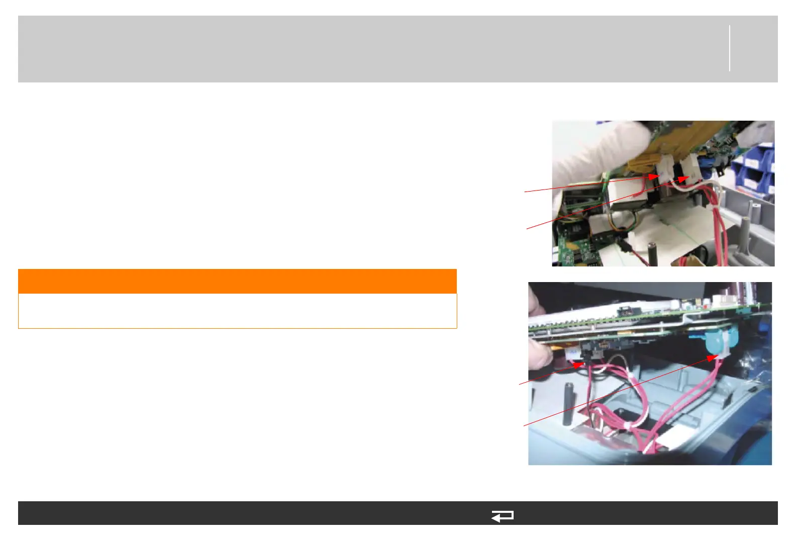
5. Connect the 5-pin connector from the A13 - transfer relay P18 to
J18 of the therapy PCB.
6. Connect the 5-pin connector from the A15 - energy capacitor to
J19 of the therapy PCB.
7. Connect the 5-pin connector from the A13 - transfer relay P21 to
J21 of the therapy PCB.
8. Connect the 2-pin connector (red and black wires) from the A13 -
transfer relay to J22 of the therapy PCB.
WARNING
POSSIBLE INABILITY TO DELIVER THERAPY Visually inspect to
ensure that P22 is fully inserted into the J22 connector.
To install the system/therapy PCB: (Continued) 15 steps, (Page 2 of 5)
J19 transfer
relay
J18 transfer
relay
J22 transfer
relay
J21 transfer
relay
Figure 8.41—System/therapy PCB cable connections