LIFEPAK 15 Monitor/Defibrillator
Service Manual
Replacement Procedures
Installing the System (A01)/Therapy (A04) PCB Assembly
Section Menu Section Contents Procedures Back Index
239
8
Installing the System (A01)/Therapy (A04) PCB Assembly
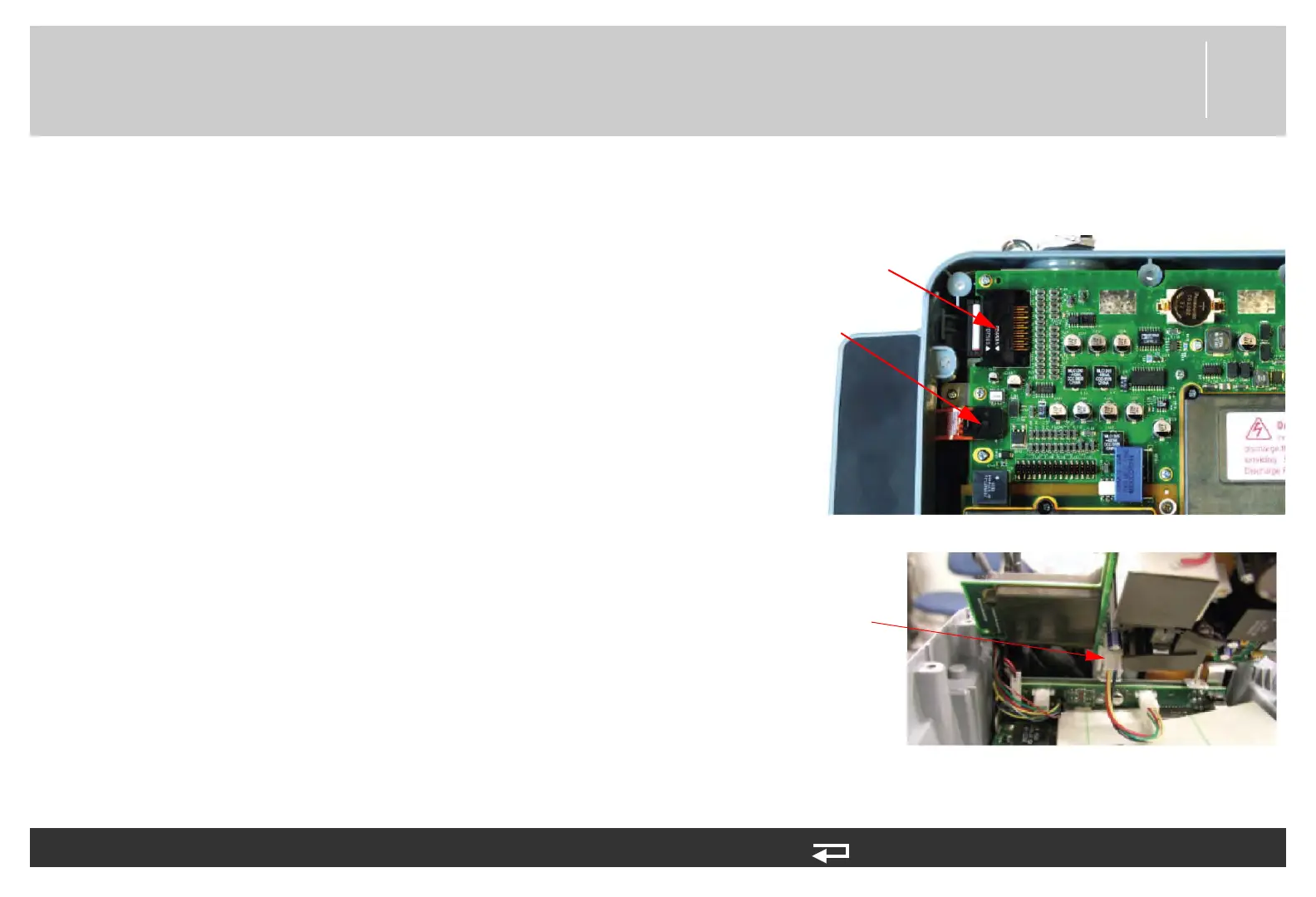
To install the system/therapy PCB: 15 steps, (Page 1 of 5)
1. Line up the system/therapy assembly with rear case.
2. Connect the W14 - USB flex cable (3206966-001) to J4 of the
system PCB.
3. Connect the W01 - power/system cable to J1 of system PCB.
4. Connect the W02 - power/therapy cable from the power PCB P20
(3009726-05) to J20 of the therapy PCB.
J1 power/
system PCB
cable
J4 USB flex
connector
J20 power/
therapy PCB
cable
Figure 8.40—System/therapy PCB connections