LIFEPAK 15 Monitor/Defibrillator
Service Manual
Replacement Procedures
Installing the System (A01)/Therapy (A04) PCB Assembly
Section Menu Section Contents Procedures Back Index
243
8
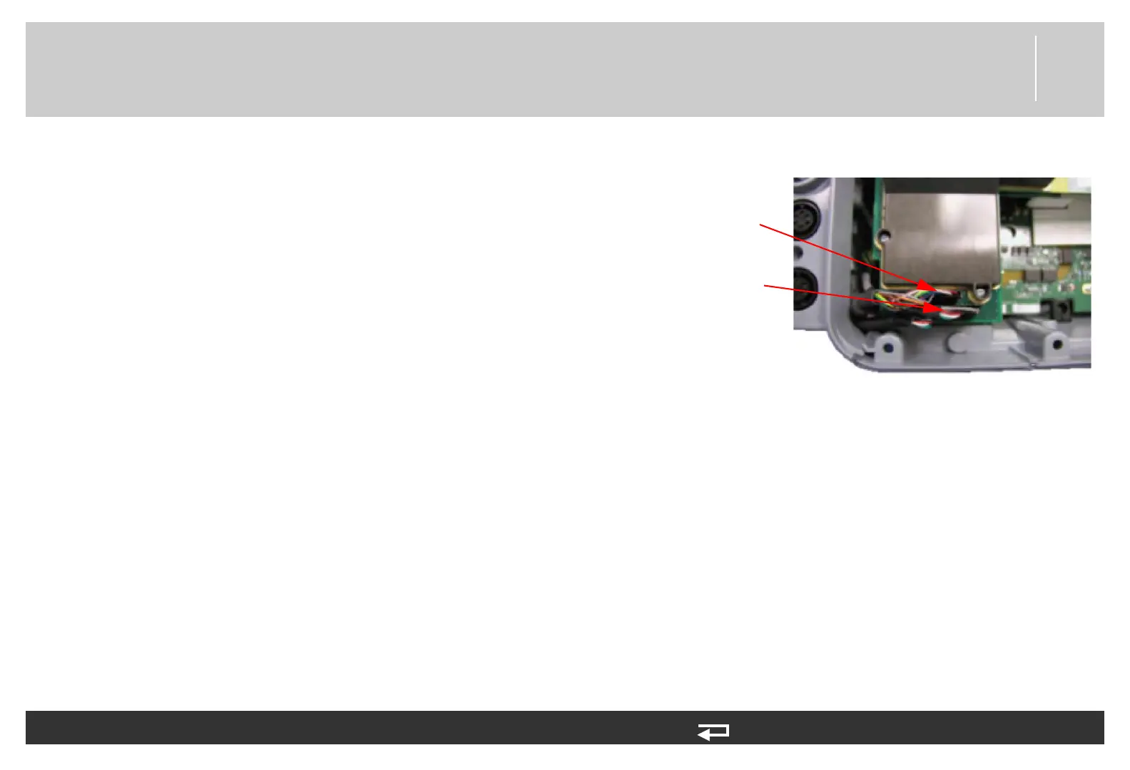
12. Connect the W07 - ECG cable from the parameter bezel to J6 of
the system PCB.
13. If present, connect the W33 - IP cable from the parameter bezel
to J7 of the system PCB.
14. If present, connect the W35 - temperature cable from the
parameter bezel to J7 of the system PCB.
NOTE: Route wires, ECG behind the connector and IP/
Temp in front of connector to reduce possible cable
pinch with the front case.
NOTE: The screw in the ECG shield can be mis-
positioned. Check to ensure that the screw is
installed and torqued.
15. Reassemble the case as described in Reassembling the Case (p.
184).
To install the system/therapy PCB: (Continued) 15 steps, (Page 5 of 5)
J6 ECG cable
J7 IP/Temp cable
(if present)
Figure 8.44—ECG and IP/Temp connections